The purpose of this I/O interface wiring guide is to allow the user to understand and deal with the connection of inputs and outputs to and from a controller board. This knowledge will a enable better understanding and provide users with more options to interface with an I/O controller.
A better understanding of electronic interface will enable the user to connect to the input with any type of sensor or switch. It can also allow output to control devices as small as a LED or as large as an appliance like a motor fan or heating oven. There is no limit to the electronic devices with which you can choose to interface or connect.
Connect Electronic Interface
The basic interface of a controller board can be simplified into 3 categories, namely
- Power Supply In
- Input
- Output
Find out how various appliances and electronic can be connected together as an integrated system working together in this I/O interface wiring guide. Connect your controller board so that you get to have full control of the system.
Power Supply In
Any electronic controller board will need a power supply to operate. The controller will typically indicate the voltage it needs and the amount of current it will consume.
A controller board which indicates a rating of 12V 0.5A indicates that it needs an input voltage of 12V, and will consume no more than 0.5A. 0.5A is the maximum possible current the controller will consume.
A 12V power supply adapter (230Vac to 12Vdc) with a current rating of 1.0A is recommended as a power supply for this board. The minimum requirement for the board example is 12V 0.5A. It is always better to use a higher rated current supply. A 12V 1.0A power supply simply means that it can supply 12V for up to 1.0A (from 0.0A to 1.0A).
There is a misconception that a power supply with higher current rate can damage the electronic controller board. The truth is choosing a power supply with too low rate current, can damage the power supply. This is because the load may draw the current it need more than what the power supply can support. The higher current draw can damage the power supply that is not designed to handle the higher current. It is recommended to use a power supply with current rating 2 times of what is required by the board. This is especially important for the old type of power supply adapter which is using a step-down transformer.
Most model electronic circuit board now uses dc-dc switching circuit onboard to regular the voltage for the electronic IC chip onboard. The advantage of using dc-dc switching regulator is that it can regulate the on-board voltage from a wider range of input voltage.
Most of the controllers are able to accept a wider range of input voltage. A controller board that can accept a wider range of voltage 5V-24V, for example, would mean that it will be easier to find a power supply to power the board. In some cases where you have another electronic device using a fixed voltage power supply, a dc-dc regulated controller can simply share the power supply. This saves you expense from buying another power supply which will take up additional space and another point on your wall electrical socket.
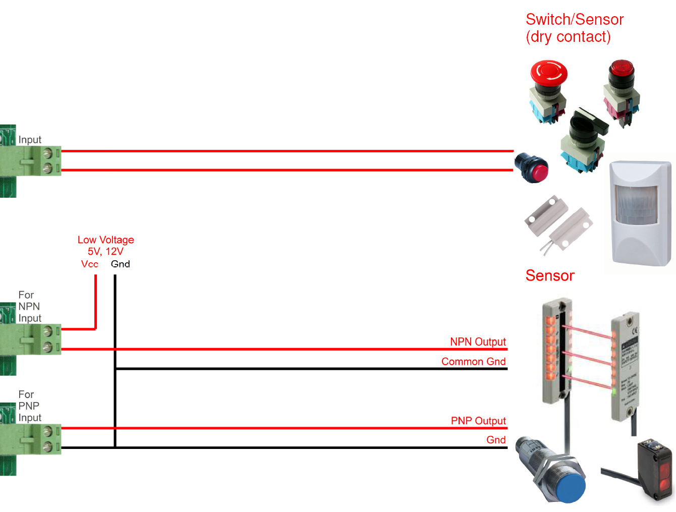
Input
Input port interface to push switched, reed switch, sensor switch, NPN & PNP sensors.
The part number PIC-113-P comes with PNP input version, while PIC-113-N is an NPN version.
You can click on the pictures to enlarge it.
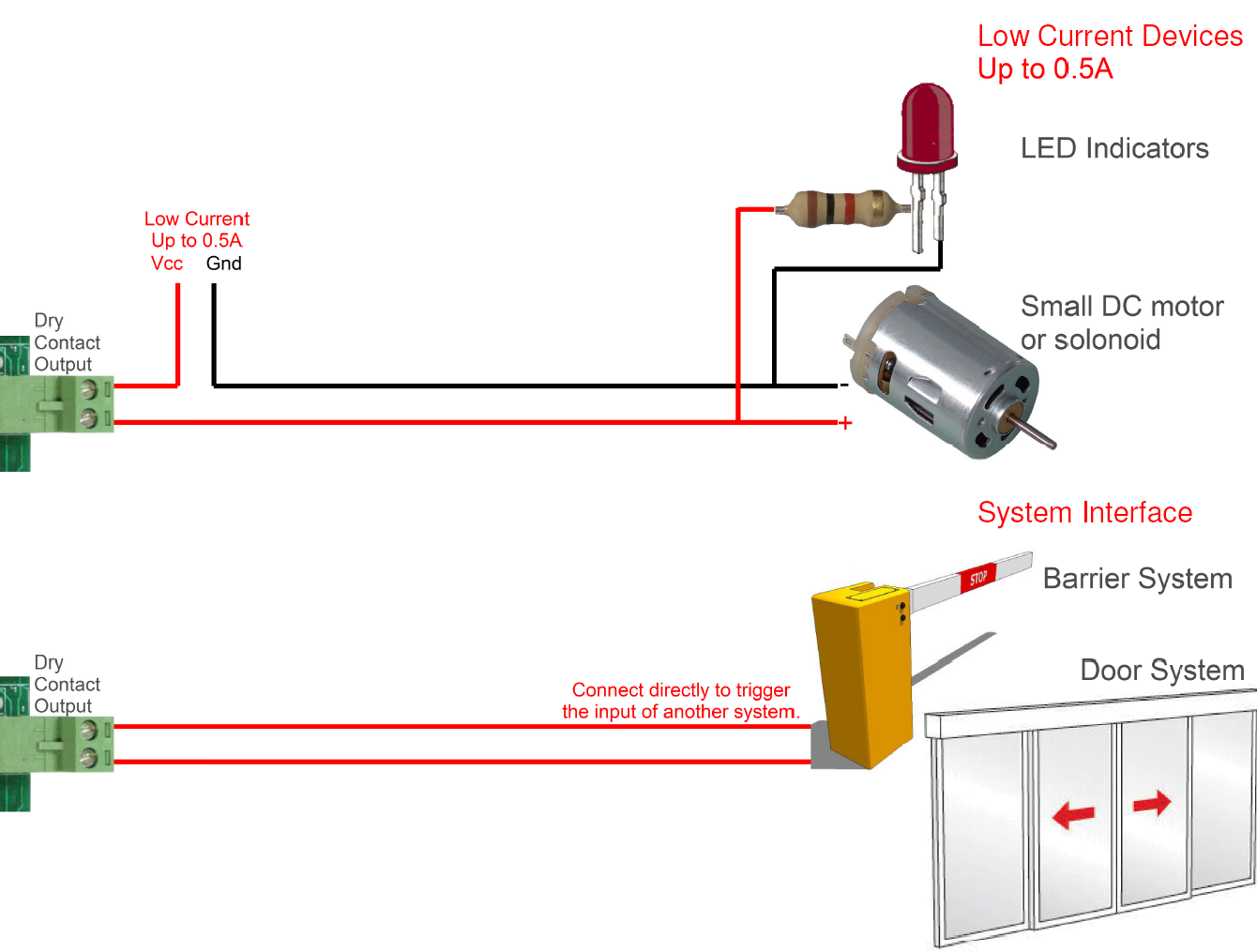
Output (Low Current)
Output port interface to low current devices. LED indicators, small motor, barrier and door control system.
The output port is a switch (dry contact) which can be used to switch the power directly to the load (LED, small DC motor). The output is able to drive output up to 300Vdc 0.5A. Any voltage or current greater than that may damage the output port.
The output being a contact switch (dry contact) can also be connected directly to the input of another control system. Most control systems have input that is able to accept switch or dry contact.
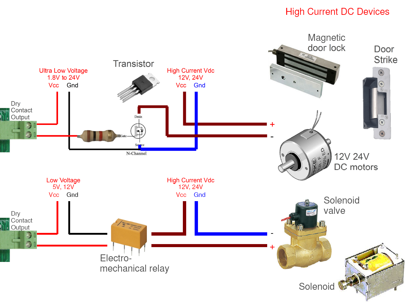
Output (High Current)
Output port interfaces to high current devices. Magnetic door lock, Door strike, DC motor, solenoid valve, solenoid.
It is also possible to drive high current devices, by using a small relay or a transistor. The relay or transistor will be activated by the output port, and switch on a larger current to drive the high current DC devices like motor, magnetic lock, solenoid, etc…
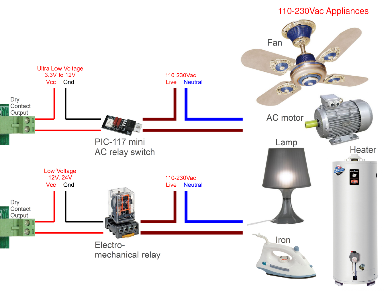
Output (High Voltage)
Output port interfaces to high voltage devices. AC fan, AC motor, Lamp, Iron, Heater.
It is also possible to drive high voltage Vac appliances, by using a higher rated relay or through the product PIC-117 mini AC relay switch.
PIC-117 is a non-mechanical relay AC switch. The relay is more robust compared to the mechanical version. It uses less energy and can be activated by a digital input as low as 3.3V.
The Right I/O Interface for Your Application
There could be many other appliances or electronic system that you need to connect or interface to. Feel free to contact PIC-CONTROL for any other types of electronic/electrical interfacing design and development.
Check out our system integration service for other difficult system connection that you need assistance with, or contact us with your I/O interface enquiry.
PIC-CONTROL can help you to Connect.
Contact PIC-CONTROL today!
![]()