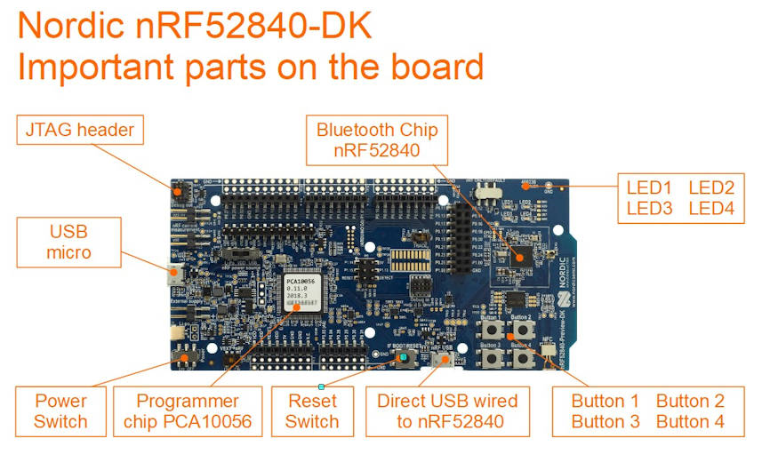
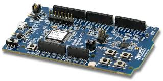
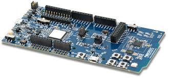
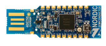
nRF52840-DK is a development kit for nRF52840 SoC (System on Chip) chip. Mainly design for Bluetooth application, supporting Bluetooth 5.0, Bluetooth Low Energy (BLE, Bluetooth 4.0).

Check out this video introduction of this nRF52840-DK development kit board.
Preparation
What do you need?
- Download Apps “nRF Toolbox for BLE” for Andriod or IOS
Demonstrate Bluetooth profile, and support Nordic UART and DFU - Download Apps “nRF Connect” for Andriod or IOS
For scanning and exploring Bluetooth Low Energy devices and communicate with them.
Support DFU and Eddystone. - Download Apps “nRF BLE Joiner” for Andriod or IOS
Proprietary method to convert Bluetooth into network devices (IPv6 nodes). - Download demo firmware from the Nordic website.
https://www.nordicsemi.com/Software-and-tools/Development-Kits/nRF52840-DK/Download#infotabs
In this example, we download the “Proximity demo“
Unzip “proximity_demo.zip”
get ready the hex file “ble_app_proximity_s132_pca10040.hex”
Inside the zip file contains readme.txt file to explain how this demo works - XXX -> Download Apps “nRF UART 2.0” for Andriod or IOS
Ways to program Nordic nRF52840 chip on the nRF52840-DK
Reference: https://devzone.nordicsemi.com/nordic/short-range-guides/b/getting-started/posts/nrf52840-dongle-programming-tutorial
https://devzone.nordicsemi.com/f/nordic-q-a/37219/how-to-upload-the-application-hex-file-uisng-usb-drag-n-drop-on-nrf52840
- Programming the nRF52840 chip, through the USB Mass Storage, vs SWD (Left side of the board)
- Programming the nRF52840 chip, through the nRF USB, vs serial USB bootloader (Bottom side of the board)
First Thing First
Download the latest SDK project files from nRF5 SDK product website. .
https://www.nordicsemi.com/eng/Products/Bluetooth-low-energy/nRF5-SDK#Downloads
The nRF5 SDK zip files contains many example projects for your to try and test.
Here is a pre-downloaded copy of nRF5 SDK ver 16.0.0 (nRF5SDK160098a08e2.zip, file size about 153MB)
in case you are having issue downloading from the official website.
Method 1 to program nRF52840 development kit via USB Storage Drive
To help you get start, to be in control of the nRF52840-DK board, I have this simple guide here to help you load in the hex file onto your nRF52840-DK board, to build up your confident.
Hex file the machine codes for the nRF52840 microcontroller chip after compiled from the source code. Nordic SDK contains both the project source code as well as the compiled *.hex file.
Here is a simplest way to test if the hex file is successfully loaded (or programmed) into the nRF52840-DK development kit.
1) Download the following files,
These 2 *.hex files are LED demonstration example which is found in the nRF5 SDK zip file that you downloaded eariler. Under the directory “examples\peripheral\blinky\hex\” & “examples\peripheral\led_softblink\hex\”. The source code can also be found in the project directory.
Please take note that there are project folder for different type of development board. One is for pca10040 development kit board, and the other is pca10056 development kit board. The one I have is PCA10056. You can take a look at the white sticker which is paste on top of your nRF52840-DK board to confirm which board you have. If you choose the wrong *.hex file, the example will not work. The files has a prefixed name “_pca10056.hex” at the back.
List of board types


2) Connect up your nRF52840 board with a micro USB cable.
You should be able to see a storage drive popping out from your computer. Inside this drive “JLINK”, you will see the following files inside.
- MBED.HTM
- README.TXT
- Segger.html
- User Guide.html
3) Copy the “blinky_pca10056.hex” hex file into the root of the JLINK drive.
This copy action will trigger a programming process of the hex file into the nRF52840 chip.
After a short second, you should see the LED1 LED2 LED3 LED4 on the nRF52840 board started to lights on in sequence, followed by lights off in sequence.
4) Next, copy the “led_softblink_pca10056.hex” hex file into the root of the JLINK drive.
After a second, you should see that the 4 LED now behaves differently. They will now fade out and fade on the lights. The old hex file can be remains in the drive. The programming action will only take place during the first time transferring of the *.hex file onto the JLINK drive.
That’s all for a simple demonstration of programming the nRF52840 chip that is on the nRF52840-DK development kit board. Simple just load in the hex file to nRF52840-DK board.
You have successfully programmed the nRF52840 chip.
Method 2 to program nRF52840 development kit via SEGGER Embedded Studio Software
1) Install and open the SEGGER Embedded Studio. If you are facing issue with the installation, you may like to visit this page for some SEGGER installation experience.
2) Open source code projects. We will use the project “blinky_pca10056”
From the menu bar go to File -> Open Solution
Open solution is like open project in other development platform. Go to the nRF5 SDK directory and select the project file “examples\peripheral\blinky\pca10056\blank\ses\blinky_pca10056.emProject“.
Folder “ses\” for the project files using SEGGER Embedded Studio.
Folder “armgcc\” is for the project files using GNU Arm Embedded Toolchain.
The project will be loaded.
In this project, you will see the file “main.c” where the blinky action codes is. Play around by modifying the code. This “main.c” file is share by other projects (defined by different board)
3) Program your new code to the nRF52840-DK board.
Ensure that you board is connect via the USB micro.
From the menu bar go to Build -> Build and Run (Ctrl+T or Ctrl+F5)
The SEGGER software will compile your code and load it to the nRF52840-DK board. It will take quite a couple of seconds to complete the up loading.
This completes your experience loading your codes using SEGGER Embedded Studio.
Play around with the other projects to get yourself familiar with the other peripherals on the chip nRF52840. Learning digital I/O pins and UART pins are the most important to help you get started in your microcontroller firmware programming. Once these two peripheral are mastered, understanding the rest will be much simpler.
For C++ coding reference, please click here to refer to this reference page.
Method 3 to program nRF52840 development kit via nRF Connect Programmer software
Check out this page.
https://www.pic-control.com/nordic-chip-programming/
Method 4 using nRF52840-DK as a programmer to program other boards
The nRF52840-DK can be used as a programmer to program other external board using the P19 Debug Header or the P20 Header Pins on the board. The DK board will detect the VTG pins for any board connected to it. If there is a connecting board, the nRF52840-DK will program the external board instead of the nRF52840 chip onboard the nRF52840-DK board.
The pins required for the programming are,
| Programmer Pins (Serial Wire Debug pins) | nRF52840 | nRF52832 | nRF51822 |
| VTG (input to detect voltage), (short to Vdd) | |||
| SWD IO | AC24 | Pin 26 | Pin 23 |
| SWD CLK | AA24 | Pin 25 | Pin 24 |
| Gnd Detect (detect ground) |
You can use ST-Link programmer to program the nRF52840 chip directly.
https://www.youtube.com/watch?v=_-d2d6Vc3lg
nRF52840-DK can act as a programmer. This programmer is J-Link compatible and can work with SEGGER software tool.
ST-Link and J-Link is not the same, but both can be use to program the chip nRF52840
Method 5 programming using a JLink Programmer
The method of programming using a Jlink Programmer is similar to the previous example of programming using nRF52840-DK as a programmer. Programming is done via the debugging header.
You can use the following JLink programmer.
- J-LINK EDU MINI (low cost)
- SEGGER J-Link EDU
- SEGGER J-Link PLUS (expensive)
Method 6 programming using the nRF Command Line Tools (nrfjprog)
Download and install nRF Command Line Tools “nrfjprog“. This program help loads the compiled firmware (*.hex) into the chip. This nRF Command Line Tools can be downloaded from Nordic website and install onto your computer.
Two things to take note before using this nrfjprog.
- Setup environment for nrfjprog.
- Ensure that the SDK points to the correct nrfjprog directory (version).
Add path to the environment variable of Win10, so that the program “nrfjprog.exe” can be accessible from any file directory. It is found in the following directory after installation.
C:\Program Files (x86)\Nordic Semiconductor\nrf-command-line-tools\bin
Ensure that the text file “Makefile.posix” in the SDK directory
F:\…..\nRF5 SDK\components\toolchain\gcc
is configured to point to the correct compiler’s install directory and version.
Begin
I am using the nRF52840-DK board (PCA10056), so we go to the following blinky project folder.
“…\nRF5 SDK\examples\peripheral\blinky\pca10056\blank\armgcc”
Inside the folder, it contains a “Makefile”. The make file contains the excuting of the program nrfjprog in sequence to load the compiled source code “*.hex” into the chip.
To flash the chip: (load *.hex into the chip)
//to program the nRF52 microcontroller chip with the hex file.
nrfjprog --family nrf52 --program $(OUTPUT_DIRECTORY)/nrf52840_xxaa.hex --sectorerase

//--> Please note that the microcontroller needs to be reset in order for the new firmware to run !!!
//Learning Notes:
//   flag --sectorerase     //to erase the memory sector (before the programming) where the code is flash onto.
//   flag --sectoranduicrerase     //to erase the memory sector (before the programming) where the code is flash onto.
//   flag --chiperase       //to erase all the user memory (before the programming) including UICR.
//reference: https://infocenter.nordicsemi.com/index.jsp?topic=%2Fug_nrf5x_cltools%2FUG%2Fcltools%2Fnrf5x_nrfjprogexe_reference.html

//verify the loaded firmware
nrfjprog --family NRF52 --verify nrf52840_xxaa.hex

//to reset the microcontroller chip after the programming
nrfjprog --family nrf52 --reset


//Example of programming a blinky firmware (LED indicator blinking firmware example)
> nrfjprog -f nrf52 --program blinky_pca10056.hex --sectorerase
Parsing hex file.
Erasing page at address 0x0.
Applying system reset.
Checking that the area to write is not protected.
Programming device.

//Example of verifying the firmware code flash in
> nrfjprog --family NRF52 --verify blinky_pca10056.hex
Parsing hex file.
Verifying programming.
Verified OK.

>>Example of flashing and verifying at one go
> nrfjprog --family nrf52 --program blinky_pca10056.hex --sectorerase --verify
Parsing hex file.
Erasing page at address 0x0.
Applying system reset.
Checking that the area to write is not protected.
Programming device.
Verifying programming.
Verified OK.

>>Example of flashing and verifying at one go, including a reset at the end.
> nrfjprog --family nrf52 --program blinky_pca10056.hex --sectorerase --verify --reset
To erase the chip:
nrfjprog -f nrf52 --eraseallTo execute this command is chip is hang.:
nrfjprog -f UNKNOWN --eraseallTip#: Using Win10 file explorer, you can simply key in “cmd” in the directory text field, the command prompt will be loaded with the path at the current window’s directory that you are at. Very convenient feature.
Nice video talking about make & cmake.
https://www.youtube.com/watch?v=fOtPq0PkqlE&feature=youtu.be
SDK configuration header file
In every project (solution), in the “Application” folder contains a file named “sdk_config.h” to allow you to configure some of the parameter of the project. To allow you to enable/disable software module in the project.
You can actually use a tool “CMSIS Configuration Wizard” in the SEGGER Embedded Studio to assist you in setting up an apps to assist you to do the configuration with ease.
https://infocenter.nordicsemi.com/index.jsp?topic=%2Fcom.nordic.infocenter.sdk5.v14.1.0%2Fsdk_config.html
First you have to go to File->Open Studio Folder…->External Tools Configuration.
You will need to paste some XML codes to enable the CMSIS tool.
Save the XML file. Close the SEGGER IDE and restart again.
This time round, go to the project application folder to look for the “sdk_config.h” file.
Right click it, you will now get to see there is a newly added option “CMSIS Configuration Wizard“
You can now use this to enable/disable your project configuration instead of editing on the precompiler code on the file “sdk_config.h”. Click on “save” after the changes. When a warning window pops up for file modified externally, click yes to have the changes updated onto the file.
What is
- DFU bootloader (Device Firmware Update)