Card Reader for CEPAS Ezlink NetsFlashPay CAN Number

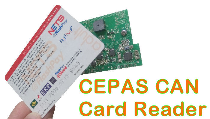
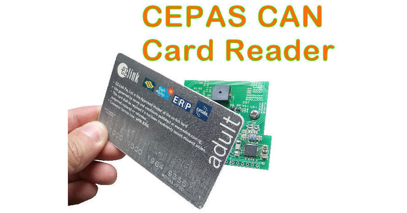
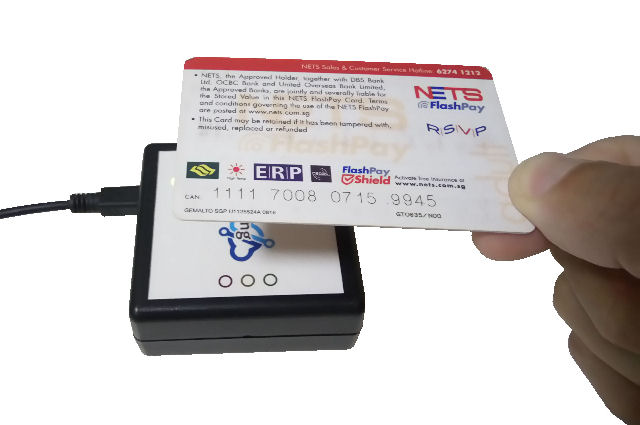
Check out this Card Reader for reading out the CAN number of local Singapore CEPAS cards, Ezlink or NetsFlashPay.

This card reader reads out the CAN number. A CAN number is a unique number which can uniquely identify the card.

Standard CEPAS CAN Card Reader Products

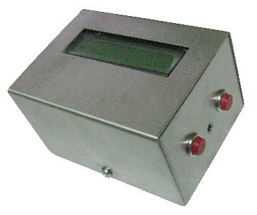
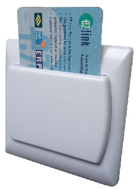
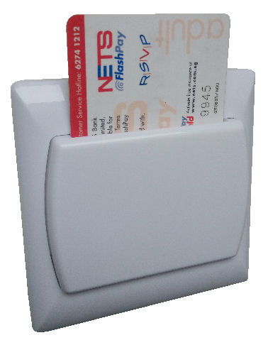
Card Key Holder

(Energy Saving)
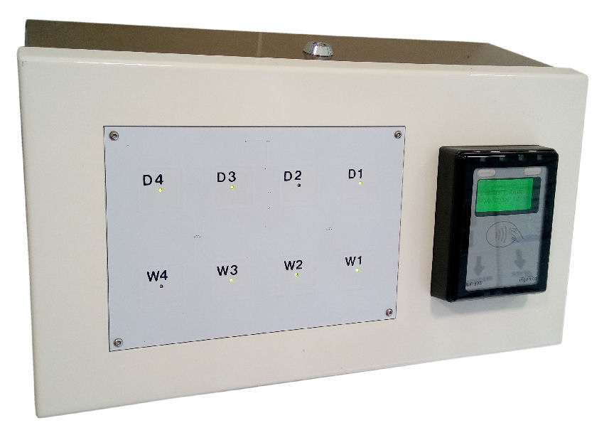
Product code: PIC-345
1) Dry Contact

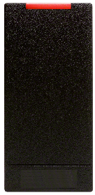
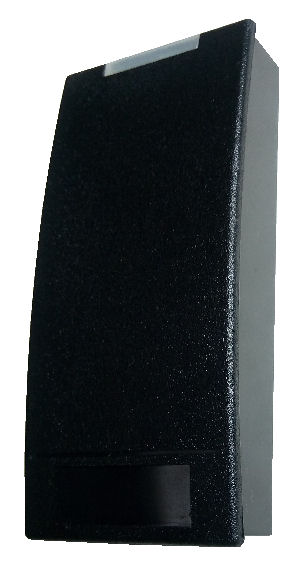
Door Access

(Wall Mounted)
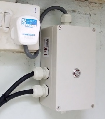
Product code: PIC-346

1) Wiegand
2) RS485
3) RS232

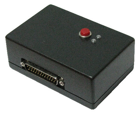
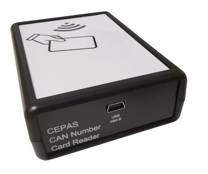
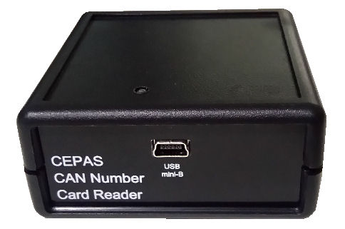
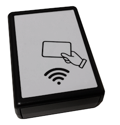
Desktop Reader

(Guest Registration)
Product code: PIC-347

1) USB Keyboard [PIC-347-HID]
2) USB Com Port [PIC-347-COM]


Ezlink CAN Card Holder CEPAS Reader (Energy Saving) CEPAS Door Access Card Reader HID Desktop USB CEPAS CAN Card Reader (Guest Registration)
CEPAS NetsFlashPay CAN Card Holder Reader (Energy Saving) CEPAS Door Access Card Reader HID USB CEPAS CAN Card Reader (Guest Registration)

CEPAS CAN Number Card Reader

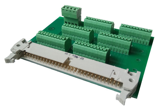
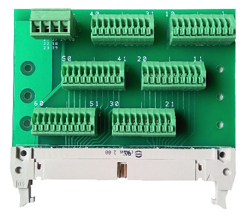
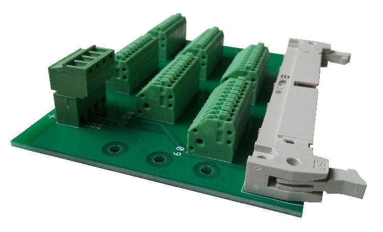
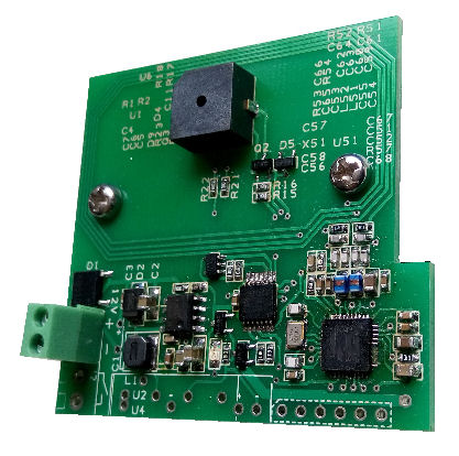
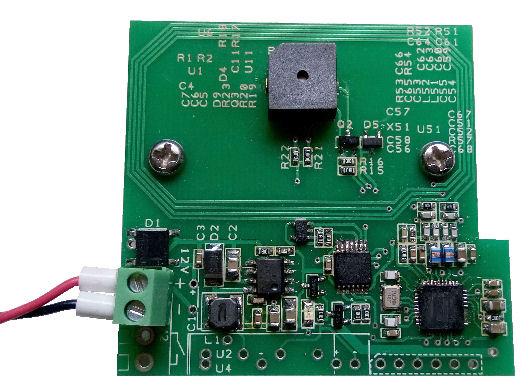
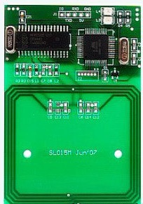
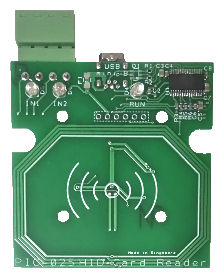
Circuit Board (Custom OEM)

This reader allows you to use publicly available cards (Ezlink, NetsFlashPay cards) for your own unique card ID application. It will save you the cost of issuing your own unique ID cards (which easily can cost you $50 per card holder). User also need not have to carry multiple cards with them.

Typical Application

  • Protect your visitor/customer privacy. Obtain unique ID of visitors or customers without revealing their identity card.
  • Using easily available CEPAS card for permanent or temporary access to private rooms without issue new cards.
  • In-house gaming or credit point system.
  • Guest visitors registration.
  • Membership registration and tracking.

If you are looking you are looking for a card payment terminal for your automated cashier, [you can click here and check out this page].

CAN number reader for NetsFlashPay and Ezlink card

Features

  • Communication connection (Custom option for Wiegand, RS232, RS485, Ethernet, USB Virtual Com Port, USB Keyboard Wedge)
  • Instant readout of the CAN number (ASCII text) of the card.
  • Buzzer feedback
  • Read light indicator
  • No need to install any software or driver (for USB Keyboard Wedge).
  • Can act as an HID keyboard for spreadsheet or text file data entry (keyboard wedge application like a barcode scanner)
  • User mode switch to select the operation mode
  • Can be customised to read any type of 13.56MHz HF RFID cards.

This card reader can be custom programmed by our engineer to read other types of 13.56MHz RFID cards/tags. Some of the cards/tags are as follows,

  • Mifare Ultralight (U1X), Ultralight C (U2X)
  • Mifare Classic Mini (S20), Classic (S50), Classic (S70)
  • Mifare Plus S (SPLUS 60), Plus S (SPLUS 80)
  • Mifare Plus X (PLUS 60), Plus X (PLUS 80)
  • Mifare DESFire EV1
  • Sony Felica, Felica Lite
  • NFC tags, NFC phone/device
  • Emulate mode to emulate RFID tags
  • ISO/IEC14443-3 Type A, ISO/IEC14443-4 Type A
  • ISO/IEC14443-3 Type B, ISO/IEC14443-4 Type B
  • NFC IP-1 mode

API and Software Technical Support

Guarantee software support to ensure everything works as you intended to be. Our engineer is ready to support and ensure that the reader that you purchase works on any of your software platform. We are here to make it work for your application.

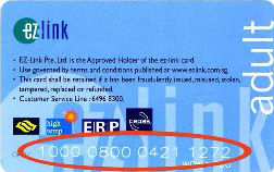
Ezlink Card (CEPAS CAN number)

Ezlink card
CAN number behind Ezlink card

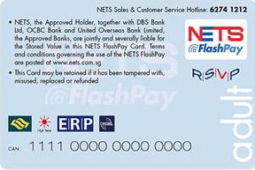
FlashPay Card (CEPAS CAN number)

NetsFlashPay card
CAN number behind NetsFlashPay card

CEPAS Compliance Cards (Co-brand)

The following types of cards can be CEPAS compliance. They can be used just like the card from Ezlink and FlashPay.

  • Passion Card membership card
  • Autopass Card (for Foreign Vehicle entering into Singapore)
  • Selected Credit Card (Standard Chartered Unlimited, Citibank SMRT, POSB Everyday Card, FEVO)

CAN Number Allocation for CEPAS Cards in Singapore

A CAN number is unique allows you to identify the cardholder group category in Singapore. This helps to identify if the card is a normal transportation payment card or a concession card. Information is obtained from Transit Link Pte Ltd.

  • 1000 xxxx xxxx xxxx (Adult CEPAS card)
  • 1009 xxxx xxxx xxxx (Adult Co-Brand)
  • 1111 xxxx xxxx xxxx (NETS Flashpay)
  • 8000 xxxx xxxx xxxx (Concession cards: Child, Pri, Sec, Ter, NS, Senior Citizen)
  • 8009 xxxx xxxx xxxx (Concession cards: Child, Pri, Sec, Ter, NS, Senior Citizen)
  • 8008 xxxx xxxx xxxx (Concession cards: Child, Pri, Sec, Ter, NS, Senior Citizen)
  • xxxx xxxx xxxx xxxx (SG Enable, Concession cards issue for the disability)

*** Note:
All concession cards do not allocate any specific CAN number for the different type of concession cards. This means that card number allocated by SG Enable  will be the same number range as the other types of concession cards. For the specific organization card number range, please write in to that specific organization for more information.

Transportation Card Around The World

More transportation card around the world for your card reader customisation.
  • Ezlink, FlashPay Card (Singapore)
  • Octopus Card (Hong Kong)
  • Touch ‘n Go (Malaysia)
  • Edy, nanaco, taspo, Waon (Japan)
  • Flazz (Indonesia)
  • Metro Card (United States)
  • Myki, Opal Card (Melbourne, Sydney)
  • PayPass, PayWave, FarePay (Credit Card Payment Network)

For the cards that you want to custom the read, you can send in 3 or more card samples. Please write down the data or text that is contained in the card that you want to read.

Custom RFID reader

Contact PIC-CONTROL for your custom RFID reader today.
We can design the communication to fit into your system. It can be Ethernet, Wifi, Modbus, Zigbee, etc…

Other RFID Products

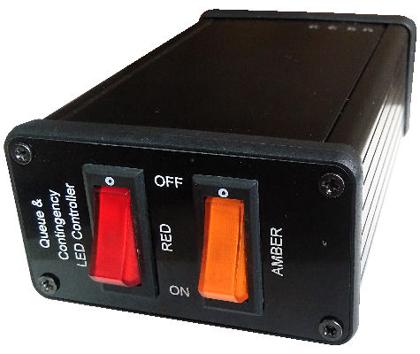
Audio Trigger Relay (Light Indicator)

PIC-024 Audio Activated Light Indicator

Audio/Sound activate relay device

Audio trigger relay cable gland to LED light indicators

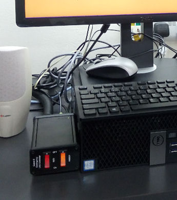
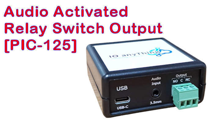
This device can detect the audio/sound from a computer system or any audio devices. Any sound detected will trigger a relay to turn “ON” which you can use to turn on a light indicator or your machinery to automate a process.

This device is also an audio triggered switch, converting audio sound into a switch output.

Features

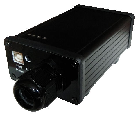
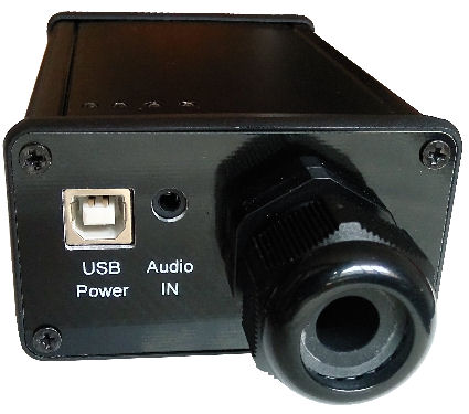
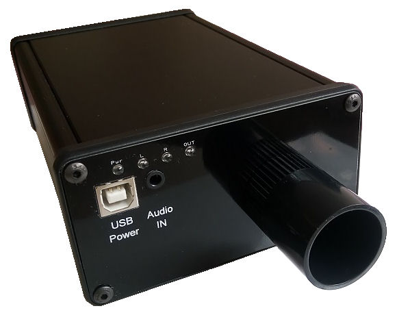
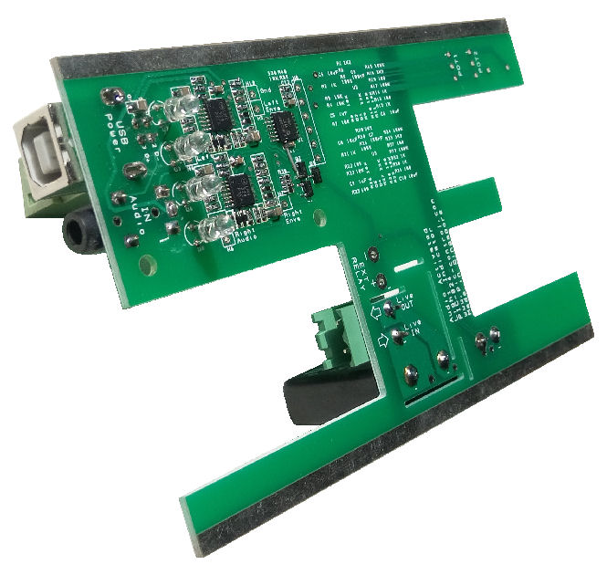
  • Sound Input Stereo Audio 3.5mm Jack.
  • Power Input USB type B socket
  • Solid State Relay Output
  • Manual Control AC Switch
  • Indicators for power, audio input and relay activated output

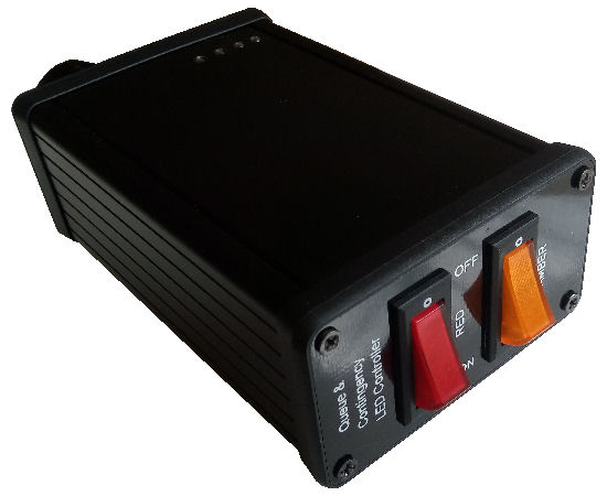
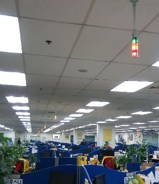
Convert the audio output from computer to a relay output for controlling lights     Controller controls tower light (Green, Amber and Red).

Application

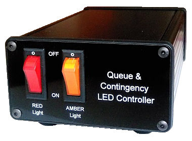
  • Call Center Queue & Contingency LED Controller
  • Convert a warning sound, or alarm from a computer to a light indicator (silent)
  • Control external automation equipment when a sound is detected
  • Convert audio from a computer to relay output.
  • Convert from sound to any I/O signal for your controller.

Example 1 :

Sometimes you need the computer system to trigger an external device when the software is sounding an alarm. For old legacy software, you may not have the source code which you can edit or do further improvement and development work. With this device, your legacy software can still trigger the alarm through the audio speaker. This device will detect the audio alarm and activate an output to trigger external system or switch on indicator or buzzer.

Example 2 :

Your existing sounder alert system can be noisy and disturbing. You can use this device to convert an existing sounder alert system into a light indicator alert. You can get your alert without disturbing others.

USB Powered

USB powered, 3.5mm Audio plug input, Power relay control.     audio input detection activated relay for light indicator

Device can be powered up from a USB port or an USB power adaptor (5V). Input socket is a USB type B.

The audio input is a 3.5mm stereo audio socket, typically use on the computer audio cable.

Manual AC Power Switch (Manual Control)

Manual overwrite AC switch to activate LED indicator lamps     LED control audio detection

Switches on the device is available for user to control the light indicator directly.

This switch will manual overwrite the audio detection function. The output will be permanently switched On.
Built-in Solid State Relay to switch 230Vac LED lamps

Audio sound triggered relay circuit board.

The circuit is built-in with a solid state relay controlling LED indicator or lamps up to 230Vac 3A.

The output can be configured to switch on the LED indicator lamp or allow the lamp blinking to get the attention of your operator.

The circuit control can also customize to power up external DC voltage devices or indicator lights.

Dry contact output to activate external equipment is also available.

Customised Sound Audio Activated Lighting Device

Contact PIC-CONTROL for customising a sound activated indicator light.

Please provide us with the detail of your application and describe how you would like the audio relay operation to function. If you have a sample of the audio sound, please send it to us for our assessment.
Alternative Product

Check out the other related products,

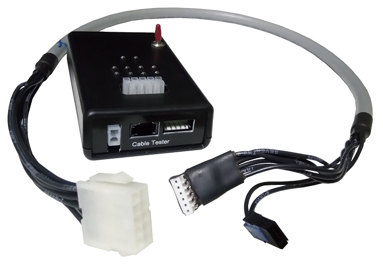
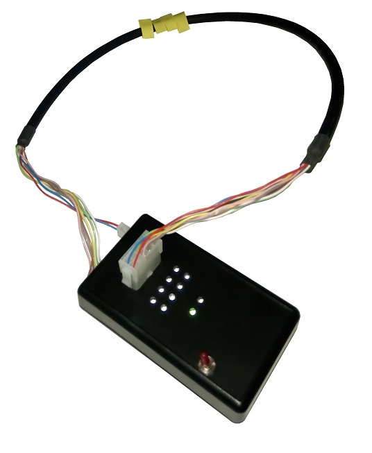
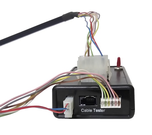
Custom Cable Tester

Cable tester, custom design for cable harness assembly production.
Custom cable tester electronic kit

An operator can just simply plug in the cable connector to the tester to check for the cable harness assembly automatically.

An audible beep will be sound immediately after the operator plug-in the connector. This indicates that the cable’s wiring is correct. The operator can simply focus their vision on the manual connection work.

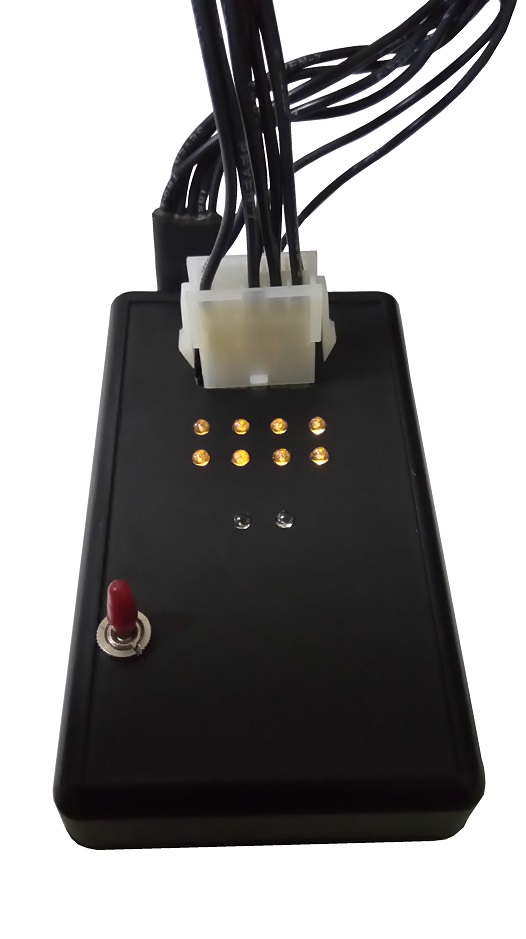
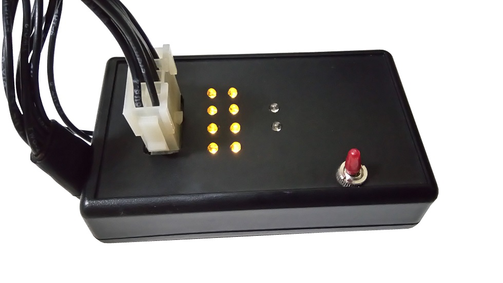
If there is no sound heard after plugging in, the cable’s wiring is probably incorrect or faulty. There will be LED indicator (orange colour) for each of the respective wiring. If any LED remains lighted up after plugging in the connector, they indicate a wiring fault. The fault due to the following,

  • incorrect pin connection.
  • the wire break resulting in a broken electrical connection.
  • the connector is not properly crimped or soldered.

Wire harness connection tester device

This custom tester has a monitoring mode which is designed to catch intermediate break wire connection that may be potentially existing in your the cable assembly. Intermediate wire connection fault can be due to a broken wire or cable that is not properly assembled. The fault may occur when the cable is touched or bend too much.

When all the connectors are connected to the cable tester, the tester will automatically enter into a monitoring mode. You should be able to hear 2 special beep sound which indicates that the tester is now in the monitoring mode. In this mode, all connectors are connected to the tester. Any connection break in the process of monitoring will trigger an error from the cable tester device.

To test your cable assembly in this mode, you can simply shake up the whole cable. The shaking can help to bring out any intermediate connection problem if there is any. You should see an error LED indicator (Red) lights up together with a long Error tone if an intermediate connection break is detected. The respective wire connection indicator (Orange LED) will also be displayed to indicate the exact wire that is having the intermediate connection problem.

Features of the Cable Tester [PIC-023]

Wire connectivity indicator lights up for faulty wires


  • Simple to use.
  • Instant audio beep and flashing LED light (Green) when the cable is plugged in, to indicate that the cable has passed the checking.
  • LED indicator (Orange) will remain lighted to pinpoint faulty wires
  • Able to catch potential intermediate connection fault in the cable.
  • LED (Red) and long buzzer tone to indicate detected cable problem.
  • Portable and can be designed to power up from USB power supply or from the battery.

Operating Procedure

Test for intermediate cable connection fault

  1. Plug in USB power cable, or insert batteries.
  2. Switch on the cable tester to power up. A test sequence will run to show that the buzzer and all the LED are working.
  3. Plug in one side of the cable onto the tester.
  4. Plug in the other side of the cable. The cable tester will detect the connection and begin testing the cable.
  5. A double beep sound and flashing Green LED indicates that the cable is tested ok.
  6. The respective LED indicator (Orange) for each of the wiring will diminish if the connection is mated correctly.
  7. If there is no sound heard after plugging in the cable, the cable is probably faulty. Check on the respective wire indicator (Orange LED) to determine the exact wire that is faulty. 1 or more LED should be lighted up which indicates incorrect or no connection.
  8. After the cable is all connected to the cable tester and has passed the wire connection test, the tester will enter into a monitoring mode. You should hear 2 special beep, followed by a blinking light from the green indicator, which tells you that the tester is now in the cable monitoring mode.
  9. In this cable monitor mode, you can continue to test the wired connection of your assembled cable harness. Shake your cable to see if there is any intermediate connection fault can be caught. If a glitch is detected due to the intermediate connection break, the cable tester device will be able to catch it. A long beep and error indicator (Red LED) will be lighted up. The respective wire indicator (Orange) will also be lighted up to pinpoint the exact wire that is causing this intermediate connection problem.
  10. The caught wire glitch fault will remain until all the wires are disconnected. The cable tester will then reset the test procedure.
  11. The operator can proceed to test the next cable harness set.

Other Optional Specialised Test Features

For dedicated wiring for precision/importance use, there are optional test that we can design to help you detect potential faults in your cable harness wiring.

The following are some of the specialised test that you may need to test on your assembled cable beside the basic connectivity check.

  • Ohm test or resistivity test for your wires and connectors, to check if the wires are crimped or fasten properly.
  • High voltage test, to ensure the wires are properly insulated.
  • High-speed data or RF test to ensure signal integrity quality of your assembled cable.

Custom Electronic Tester

Contact PIC-CONTROL for further information for your custom cable tester.

custom cable harness tester design

Cathodic Protection

Cathodic protection is a popular maintenance prevention measures to protect the metal steel structure from corrosion from the harsh environment. This is especially in the marine industries where metal structures close to the sea water are prone to corrosion.

The cathodic protection system is very commonly used by the shipping industry in Singapore and Malaysia. They are deployed on large steel structure to prevent corrosion. Applied to the ship or yacht’s hull to protect against marine growth.

cathodic protection driver electronic circuit board

Besides cathodic protection, there are also other protection system and technology. Other methods to protect and maintenance metal steel are:

  • Maintenance painting or resist coating on the metal to isolate it from the harsh environment.
  • Apply of corrosion inhibitors to the metal.
  • Chemical dosing the pH of the environment.
  • Using a more corrosion resistant material.

The cathodic protection system is a technology that works by conducting the metal steel structure (making the metal steel structure to be protected as a cathode) and an anode with a controlled AC power. The voltage waveform is generated from a station and is conducted onto various isolated metal steel pipelines or metal structures.

Application

  • Protect metal steel pipes and storage tanks from corrosion.
  • Marine growth prevention on ship’s hull.
  • Protect equipment.
  • Underground metal pipelines protection.
  • Shielding of buried or submerged metal structure.

Products

Cathodic protection products from
Eastern Electrical Mechanical Engineers Pte. Ltd. logo Eastern Electrical Mechanical Engineers Pte. Ltd. (EEME)

cathodic protection driver electronic circuit board

Cathodic Protection Solution Service Provider

Eastern Electrical Mechanical Engineers Pte. Ltd. logo

Eastern Electrical Mechanical Engineers (EEME) is a company providing cathodic protection solution, supplies and manufacture cathodic protection products.

EEME has been delivering electrical system and cathodic protection solution to customer in South East Asia (Singapore, Malaysia, Indonesia, Thailand, Brunei), India, United Kingdom, Canada and Brazil.

Contact Eastern Electrical Mechanical Engineers for your cathodic protection solution.

Related reference:


Clone Microcontroller Chip

PIC-CONTROL provides cloning of your microcontroller IC chip (MCU) for your documentation and production use.

Many of our clients do not have their project source code (firmware) for their microcontroller circuit board product. The documentation was not properly kept and are lost in the transition when their key developer left the company.

PIC-CONTROL provides PCB copying, reverse engineering of electronics design and firmware development services to help you recover and safeguard your product documentation.

Cloning Microcontroller Chip Explain

The chip cloning process is not too difficult. The idea of cloning or copying a microcontroller chip is to extract out the machine code from the original microcontroller and write the same codes to a new microcontroller chip. The machine code is also sometimes known as the hex code. It is typically loaded as a file format with an extension “*.hex”. Some detective work is expected especially if the chip’s branding and the part number is not disclosed. Having experience helps speed up the detective work.

The first step is to identify the chip’s manufacturer and the microcontroller part number. Sometimes the production batch number or the chip’s version number is important too. The machine code used for an old chip version may not work correctly when loaded onto your new chip. So it is important to take note of the version. In today’s context, this poses less of an issue.

A software and a programmer are required to extract out the machine code. Before we even use these tools, we also need to understand how more about the microcontroller that is to be cloned. The datasheet of the microcontroller can be obtained from the chip’s manufacturer. Study the chip for its pin out. Know where the power supply and programming pins are. Design and construct a circuit for the microcontroller to allow the programmer to interface it to the software on your computer.

Through the software, we can then extract and download the machine code into a *.hex file on our computer. This *.hex will be the machine code that is required for the future production of the microcontroller.

  • Check manufacturer, part number and batch version.
  • Study microcontroller datasheet.
  • Build and construct a programmer interface circuit.
  • Connect up the software and programmer for the extraction process.
  • Extracting the machine codes (hex code) by reading from the microcontroller IC chip.
  • Archive the machine code in a *.hex file.
  • Uploading of the machine code onto a new microcontroller IC chip.
  • Reading of the microcontroller EEPROM (flash memory) to verify the data.
  • Code protected microcontroller.

Common Questions

Some questions people may ask or will be concern about,

  • Is it the same?
  • Will it be reliable?
  • Will the original chip be damaged in the cloning process?

The cloning of the microcontroller chip will be perfectly the same as your original version. It will be as reliable as your original version because the chip is from the same chip product manufacturer. If there is a problem, usually it is a manufacturer’s defect or may have cloned to a wrong chip or a different chip batch version.

The chip will be handled with care. Do let us know if the chip to be clone is the one and only piece available.

Cloning May Fail

Microcontroller cloning may fail. A microcontroller has code protection features which help prevent their competitors from stealing their intellectual property work. If the code protection feature is enabled, the codes that are extracted from the original microcontroller will not work at all.

An alternative solution to this will be to do reverse engineering and re-development work of the circuit board project.

Microchip Microcontroller OTP Chip Series

A typical microchip microcontroller comes with 2 series. One is the PICxxFxxx, and the other one is the PICxxCxxx.

The ‘F’ denotes a reprogrammable EEPROM or Flash series microcontroller which allows you to reprogrammable the chip many times.

The ‘C’ denotes an OTP (One Time Programmable, EPROM) microcontroller which only allows you to load in your firmware only once. Most of these ‘C’ series chip is going into obsolete.

PICkit3 programmer does not support for these ‘C’ series chip. The programmer requires a higher voltage and current for the programming of the chip. The good news is that there is usually an ‘F’ series chip which can be a direct replacement for the ‘C’ series chip.

Modify or Improving Microcontroller Firmware

Improving your existing microcontroller firmware will not be possible without the source code on hand. A source code is an algorithm written to operate the microcontroller chip.

Cloning of IC chip only reads out the machine codes that is stored in the chip. The codes are then written into a new chip. While it is not something impossible to edit the machine code, it will probably take up a lot of time and effort to do it. All these will translate to a higher engineering expense.

In a situation where you need to improve the microcontroller’s algorithm but you do not have the source code on hand, we will recommend to re-write your firmware. The firmware development work will involve reverse engineering of your circuit board, and coding of a new firmware which will operate similarly to your existing version. The work usually also involve copying of the PCB circuit and hacking/cracking of the design from your original circuit board.

The benefit of redevelopment work is that you will be able to recover the design documentation blueprint (schematic, PCB design file, and source code) which you will be able to use for your future production. In a situation of components obsolete, you can easily seek for alternative replacement with the project documentation on your hand.

Check out our microcontroller IC chip firmware programming services for

EEPROM Cloning and Duplication Services

PIC-CONTROL provides IC chips cloning and duplication services for Microchip and ATMEL microcontrollers.

Microchip Microcontroller Part no.

ATMEL Microcontroller Part no.

  • ATtiny44A
  • ATmega328
  • ATmega16U2
  • ATmega32U4
  • more ATMEL microcontrollers…

What You Need to Provide Us

The following is a guideline of the information that we will need for assessing your microcontroller cloning project,

  1. The microcontroller chip part number
  2. Photos of the circuit board operated by the microcontroller.
  3. A detailed description of the application driven by this microcontroller.

*** We will not be able to help if any of the above information is not sufficiently provided.

Typical cloning cost is about $300 if it is NOT protected. Most of the time the chip is protected. We will not be able to clone a protected chip. An alternative way will be to reverse engineer your electronic circuit. Depending on the complexity of your circuit, reverse engineering cost can range from $500 to more than $30K. Check out our reverse engineering page for more information on the process.

Contact PIC-CONTROL to clone and copy microcontroller IC chips today.

PIC-CONTROL also provides circuit board copying and reverse engineering services

Click on the relevant links for more details on how we can help you to clone your electronic circuit board.

PIC-CONTROL provides electronic engineering services to our client in Singapore.

Check out our website for more details.

PCB copy service in Singapore

Reverse engineering of electronic circuit board

Electronic Trigger RS232 Control Board

Electronic trigger output with RS232 control board

This is an RS232 electronic trigger board which is controlled via an RS232 communication cable. Any computer or controller can send a command through the RS232 line and trigger a dry contact output (or optical isolated NPN output) to control external devices like door or barrier.

Product Code [PIC-026]

The activated output allows you to trigger a signal to activate other external interfacing devices. If you need to use this output to control high power/current devices, you can interface this output via a higher current rated relay.

A quick test push button (optional) is available on the board which allows you to trigger the output manually without having to send the command via RS232.

The board feature a controller which the algorithm can be customised to any of your special requirements.

Application

  • trigger open for vehicle barrier control
  • vending machine
  • coin acceptor trigger emulator
  • open motorised sliding door
  • release security EM lock (electromagnetic lock) or door strike for the office door
  • trigger other external controllers
  • via an external relay switch to power on high power appliances like lighting, motor, etc…

RS232 control trigger output

Features

  • 1x dry contact relay output trigger. (for up to 24V 0.5A signal)
  • Power up from a wide voltage range 7V, 9V, 12V-24V (0.5A).
  • Convenient test button.
  • On-board adjustable output pulse timing (20mSec to 1000mSec).
    (new model only) Adjustable POT for configuring pulse timing from 10msec to 1sec
  • Precise pulse timing can be adjusted through RS232 commands.
  • Selectable output trigger, NO (normally open) or NC (normally close).
  • Small board size measuring 71 x 28mm, light in weight.
  • RS232 communication (Can use normal RS232 (DB9) cable or cross cable).
  • Default RS232 settings: 9600bps, 8bit data, 1 stop bit, no parity.

Optional Features

  • Learning mode to clone pulse timing from an external device (e.g a coin or notes acceptor).
  • Can become a sensor to detect pulse width from an external device.
  • Opto-isolated npn transistor output trigger. (or solid state output)

Please specify your requirements or application if you require these optional features.

Dimension

RS232 electronic trigger control board (layout & dimension)

Custom RS232 Electronic Trigger Control Solution

*** Check out more RS232 Pulse Switch OUTPUT Trigger device information here. ***

Contact PIC-CONTROL for your customised electronic trigger control solution.

You can also check out our website for other electronic engineering services and electronic products.

Test Jig Tray Testing IC Chips Electronic

Easy to pick up IC chip from reflow tray

Reflow Tray for IC Chip Testing

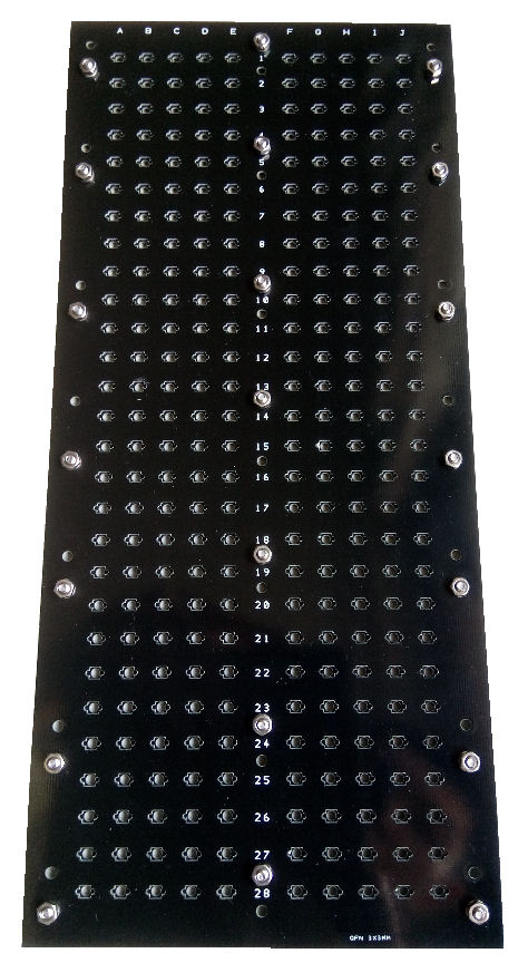
Reflow tray for testing of IC chip through a PCB board reflow soldering machine. Test jig holding tray for IC chip testing.

Available reflow tray design

  • RT-000 (base plate to protect the bottom of the board)
  • RT-001 (middle plate to support the IC chip)
  • RT-002 (top plate to hold the chip in position)

RT-002 Reflow Tray for testing IC chip

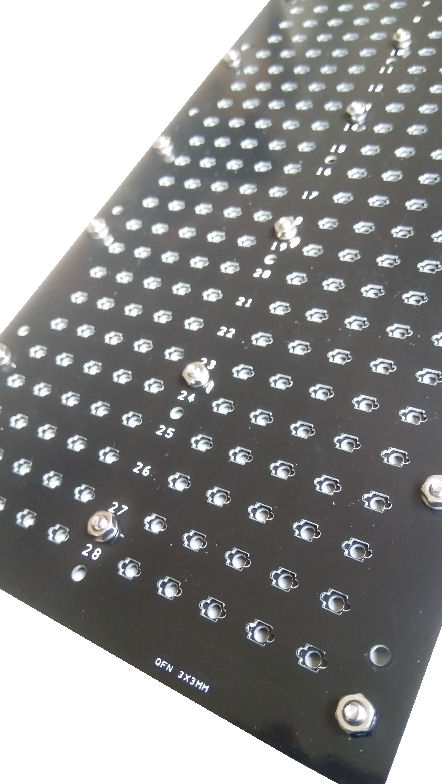
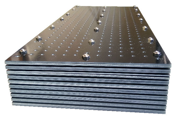
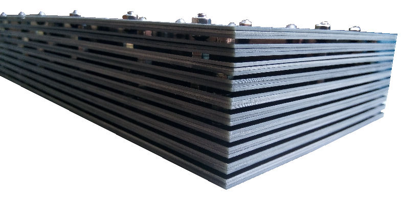
PCB board milling for different layers creating a 3D test tray for holding IC chip in position.

RT-002 Reflow Tray, fixture jig for IC chip testing

Specification

  • Board thickness 3.2mm.
  • Green soldering mask on PCB board. (also available in Black color mask)
  • Text printing using white silk screen.
  • Designed to hold 20pcs of BGA IC chips.
  • IC chip holder space tolerence ±0.2mm
  • Reflow tray size (100 x 100mm)
  • 12x alignment holes (⌀3mm)
  • Secure by 4x Button cap screw M3x6, a spring washer and a nut

Dimension

RT-002 Reflow Tray Dimension

Use Instruction

  1. Place the IC Chips (test subject) on the reflow tray.
  2. Position the tray with the IC chips on a reflow soldering oven or the reflow soldering conveyor belt.
  3. Reflow soldering takes about 5mins, with a temperature reaching a peak of about 250°C.
  4. Allows the tray to be cool, and pick up from the reflow machinery.
  5. Allow the tray to cool down before using it for the next round of reflow testing.

Reflow Tray for IC chip testing

The PCB will turn dark green under normal usage after using it for a number of times.

Warning: If the tray is being over heated, the green mask can start to be decolourised. Burned mark with brown black color can be observed.

Typical Reflow Soldering Profile

  1. Preheat (to 150°C in 60 sec)
  2. Soak (from 150°C to 165°C in 120 sec)
  3. Reflow (reaching peak temperature of 225°C to 235°C, holding it for about 20 sec)
  4. Cooling (-4°C/s or free-air cooling)


Water Dispenser Kiosk

Workflow Procedure for Water Dispenser Kiosk

  1. A customer inserts their wireless card (Ezlink or NETS FlashPay card) to the water dispenser kiosk. The system holds the card.
  2. The system checks the remaining balance on the card, and estimate the max amount of water it can release base on the card balance.
  3. The user dispenses out the amount of water he needs. There is a real-time display to present to the user the amount dispensed and the cost incurred so far. The user cannot dispense more than the estimated maximum amount water (determined by the remaining balance amount on the card).
  4. Once the user finishes dispensing, the user will hook back the dispenser or eject the card. It is also an acknowledge from the user to proceed with the payment.
  5. The water dispenser kiosk will deduct from the card base on the amount of water dispensed.

Other Reference


Washing Machine Centralised Kiosk Payment System

Cashless payment kiosk for your laundromat.
from Fresh Laundry Pte. Ltd.

Payment Kiosk User Guide

Integrated Washing Machine Payment System
Washing machine from Fresh Laundry

  1. The customer put clothes into a washing machine available.
  2. Customer press a start button on the washing machine to trigger for payment.
  3. The washing machine will inform the payment kiosk to collect the payment.
  4. The customer walks to the nearest payment kiosk and flashes their cashless card (Ezlink, NETS FlashPay, PayWave, PayPass card) for payment.
  5. Payment kiosk will then instruct the washing machine to proceed with the wash after the payment is completed.

Custom Centralised Kiosk Payment System

Contact PIC-CONTROL for your customised kiosk payment system.

Integrated Washing Machine System Washing machine from Fresh Laundry

Other Reference

Alliance Laundry System (Laundromat)

Alliance Laundry System (Laundromat)

Speed Queen Washer/Dryer Wiring Connection

Central Cashless Payment Terminal
Ez-Link payment   NETS FlashPay payment   Visa PayWave payment   MasterCard Pay Pass payment   SG QR code payment

                                        Cashless Payment Terminal


Reference Guide

Click here for the payment system installation for Speed Queen Dryer and Washing machines.


Alert Alarm System | Sounder and Beacon

PIC-CONTROL customised alert alarm system. The sounder beacon provides a visual stroke light and warning siren sound to alert people of a dangerous situation ahead. A wide range of warning siren sounds to choose from with adjustable volume. Custom features like wireless remote, SMS/email messaging alert or sensor automation can be integrated to suit your application.

Sounder beacon alert signage

Sounder Beacon

  • Stroke Light (Amber or Red colour)
  • 32 siren tones to choose from. Alert, alarm or warning.
  • Adjustable volume from soft to very loud. (110dB peak at 1m, 10-50m outdoor depending on the environment)
  • Weatherproof IP65.
  • Compliance EN54 3:2001
  • For indoor and outdoor use
  • Voltage supply 17-60Vdc (50mA)

Wireless Remote Control

wireless remote control (for long distance control)

  • Remote control distance of 100-200m in open space.
  • 12Vdc (50mA)
  • Latched or momentary switch.

Sounder Beacon Control Box

sounder beacon wireless remote control boxwireless sounder beacon control box

Setting off the alert with a manual switch is available as an alternative to activated the system via remote control.

Wiring Diagram for Sounder Beacon with Wireless Remote Control

The following diagram shows an example of a complete wiring diagram of a wireless remote control sounder beacon alert system.

Wiring diagram for wireless sounder beacon system

Other Customisation

Drop us an email for your required alert system. Our sales engineer will get back to you shortly with a quote.