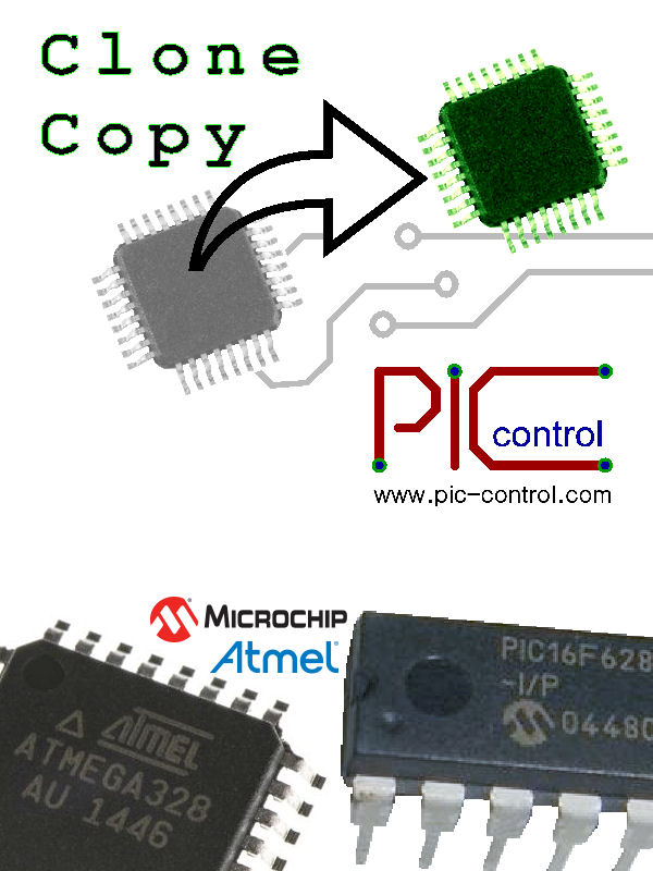
PIC-CONTROL provides cloning of your microcontroller IC chip (MCU) for your documentation and production use.
Many of our clients do not have their project source code (firmware) for their microcontroller circuit board product. The documentation was not properly kept and are lost in the transition when their key developer left the company.
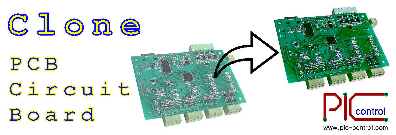
PIC-CONTROL provides PCB copying, reverse engineering of electronics design and firmware development services to help you recover and safeguard your product documentation.
Cloning Microcontroller Chip Explain
The chip cloning process is not too difficult. The idea of cloning or copying a microcontroller chip is to extract out the machine code from the original microcontroller and write the same codes to a new microcontroller chip. The machine code is also sometimes known as the hex code. It is typically loaded as a file format with an extension “*.hex”. Some detective work is expected especially if the chip’s branding and the part number is not disclosed. Having experience helps speed up the detective work.
The first step is to identify the chip’s manufacturer and the microcontroller part number. Sometimes the production batch number or the chip’s version number is important too. The machine code used for an old chip version may not work correctly when loaded onto your new chip. So it is important to take note of the version. In today’s context, this poses less of an issue.
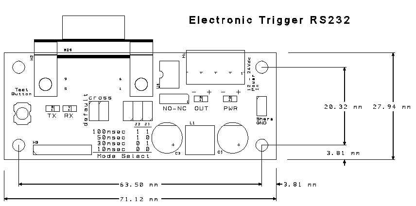
A software and a programmer are required to extract out the machine code. Before we even use these tools, we also need to understand how more about the microcontroller that is to be cloned. The datasheet of the microcontroller can be obtained from the chip’s manufacturer. Study the chip for its pin out. Know where the power supply and programming pins are. Design and construct a circuit for the microcontroller to allow the programmer to interface it to the software on your computer.
Through the software, we can then extract and download the machine code into a *.hex file on our computer. This *.hex will be the machine code that is required for the future production of the microcontroller.
- Check manufacturer, part number and batch version.
- Study microcontroller datasheet.
- Build and construct a programmer interface circuit.
- Connect up the software and programmer for the extraction process.
- Extracting the machine codes (hex code) by reading from the microcontroller IC chip.
- Archive the machine code in a *.hex file.
- Uploading of the machine code onto a new microcontroller IC chip.
- Reading of the microcontroller EEPROM (flash memory) to verify the data.
- Code protected microcontroller.
Common Questions
Some questions people may ask or will be concern about,
- Is it the same?
- Will it be reliable?
- Will the original chip be damaged in the cloning process?
The cloning of the microcontroller chip will be perfectly the same as your original version. It will be as reliable as your original version because the chip is from the same chip product manufacturer. If there is a problem, usually it is a manufacturer’s defect or may have cloned to a wrong chip or a different chip batch version.
The chip will be handled with care. Do let us know if the chip to be clone is the one and only piece available.
Cloning May Fail
Microcontroller cloning may fail. A microcontroller has code protection features which help prevent their competitors from stealing their intellectual property work. If the code protection feature is enabled, the codes that are extracted from the original microcontroller will not work at all.
An alternative solution to this will be to do reverse engineering and re-development work of the circuit board project.
Microchip Microcontroller OTP Chip Series
A typical microchip microcontroller comes with 2 series. One is the PICxxFxxx, and the other one is the PICxxCxxx.
The ‘F’ denotes a reprogrammable EEPROM or Flash series microcontroller which allows you to reprogrammable the chip many times.
The ‘C’ denotes an OTP (One Time Programmable, EPROM) microcontroller which only allows you to load in your firmware only once. Most of these ‘C’ series chip is going into obsolete.
PICkit3 programmer does not support for these ‘C’ series chip. The programmer requires a higher voltage and current for the programming of the chip. The good news is that there is usually an ‘F’ series chip which can be a direct replacement for the ‘C’ series chip.
Modify or Improving Microcontroller Firmware
Improving your existing microcontroller firmware will not be possible without the source code on hand. A source code is an algorithm written to operate the microcontroller chip.
Cloning of IC chip only reads out the machine codes that is stored in the chip. The codes are then written into a new chip. While it is not something impossible to edit the machine code, it will probably take up a lot of time and effort to do it. All these will translate to a higher engineering expense.
In a situation where you need to improve the microcontroller’s algorithm but you do not have the source code on hand, we will recommend to re-write your firmware. The firmware development work will involve reverse engineering of your circuit board, and coding of a new firmware which will operate similarly to your existing version. The work usually also involve copying of the PCB circuit and hacking/cracking of the design from your original circuit board.
The benefit of redevelopment work is that you will be able to recover the design documentation blueprint (schematic, PCB design file, and source code) which you will be able to use for your future production. In a situation of components obsolete, you can easily seek for alternative replacement with the project documentation on your hand.
Check out our microcontroller IC chip firmware programming services for
EEPROM Cloning and Duplication Services
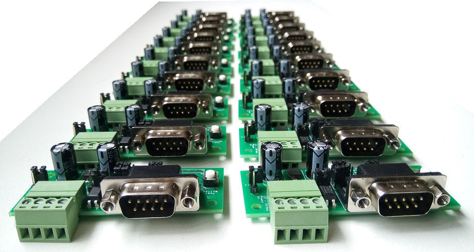
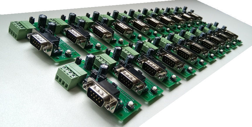
PIC-CONTROL provides IC chips cloning and duplication services for Microchip and ATMEL microcontrollers.
Microchip Microcontroller Part no.
ATMEL Microcontroller Part no.
- ATtiny44A
- ATmega328
- ATmega16U2
- ATmega32U4
- more ATMEL microcontrollers…
What You Need to Provide Us
The following is a guideline of the information that we will need for assessing your microcontroller cloning project,
- The microcontroller chip part number
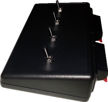
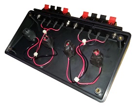
- Photos of the circuit board operated by the microcontroller.
- A detailed description of the application driven by this microcontroller.
*** We will not be able to help if any of the above information is not sufficiently provided.
Typical cloning cost is about $300 if it is NOT protected. Most of the time the chip is protected. We will not be able to clone a protected chip. An alternative way will be to reverse engineer your electronic circuit. Depending on the complexity of your circuit, reverse engineering cost can range from $500 to more than $30K. Check out our reverse engineering page for more information on the process.
Contact PIC-CONTROL to clone and copy microcontroller IC chips today.
PIC-CONTROL also provides circuit board copying and reverse engineering services.
Click on the relevant links for more details on how we can help you to clone your electronic circuit board.
PIC-CONTROL provides electronic engineering services to our client in Singapore.
Check out our website for more details.

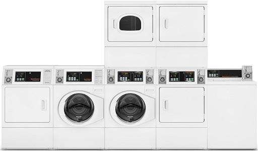
 Washing machine from