Testing & Compliance Labs

Testing and Compliance Laboratories in Singapore for electronic products (electronic product certification),

TUV SUB PSB http://www.tuv-sud-psb.sg/
SETSCO http://www.setsco.com/
Singapore Test Services http://www.test.com.sg/
SGS (test laboratory in China) http://www.sgs.sg/
NorthLab Pte Ltd (A Trescal Company) http://www.northlab.biz,
http://www.trescal.com
Spring Singapore for Singapore Safety Mark email: safety@spring.gov.sg
UL Solutions https://www.ul.com/

Test labs worldwide, http://www.nea.gov.sg/energy-waste/energy-efficiency/household-sector/test-laboratories

EMC compliance, Class A, Class B, EN 55011 Class A with EN61000-6-2

Emergency Lamp compliance (SS563, SS263)

  • 1-SS 563 Part 1 2010, Code of Practice, Emergency   lighting
  • 1-SS 563 Part 2 2010, Code of Practice, Installation   requirements and maintenance procedures
  • 2-SS 263 Part 2 1998, Specification for Luminaries
  • 2a-SS 263 Part 2 1998, Amd1_SS 263-2-1998
  • 2b-SS 263 Part 2 1998, Amd2_SS 263-2-1998
  • IEC 60598-2-22 : 2014

CE Certification

CE-marking services from SGS

CE marking services from TÜV SÜD PSB

RoHS Compliant

Is your product RoHS compliant?

RoHS2 Directive

PCB Design – Tips on laying out a good PCB board

Designing electronic circuit is only the beginning of translating an idea into a physical product. The next important step is to translate your schematic design into a layout on a PCB board. This is known as PCB circuit design. A PCB board provides the platform to hold electronic components (IC chip, resistors, capacitors, inductors, etc…) and enable their connection (known as PCB traces). It is also the main means to replicate the connections for mass production purpose. Most PCB boards are green in colour (we call it green coloured mask).

PCB circuit board design and layout service in Singapore

For small quantity production or simple electronic circuit prototype, PCB circuit design is usually not required. This is because designing the layout for the circuit can take up engineering effort. A typical simple circuit can take from 3 to 7 days to design and layout. This is a fixed cost prior to your production. Good news is that you only need to do it once. With this PCB blueprint (commonly refer to as Gerber files) you can reproduce as many PCB board as you like. For larger mass production quantity, the circuit design and layout cost is usually insignificant compare to the cost of each board. If you are only producing a few pieces of a simple electronic design for prototype testing purpose, this engineering effort may not be worth the value. It maybe cheaper to use a prototyping board instead to build and test your design.

PCB Design

The PCB circuit design is a combination of knowledge in electronic and user interface art. Engineering know-how to ensure the circuit works without issues, and also to design it in a simple manner such that the people using the circuit board product can easily handling it.

Engineering Know-How

Design PCB board requires a certain skill set. Besides the basic knowledge of electronic, a good foundation in the area of RF (Radio Frequency) is preferred. It may seem odd so some. What is RF going to do with PCB design? Wireless and PCB is a different topic, aren’t they? No. In fact, they are very much closely related. Knowledge of RF provides us with a strong understanding of how electronic circuit behaves under high-frequency condition. It is also related to how the electronic components and traces should be layout in order to keep the signal integrity within an acceptable tolerance, keeping the noise (unwanted signal) minimum. This is especially important when your electronic design contains sensitive analogue circuit, high-speed digital circuit or RF circuits. There rules to follow to ensure that the electronic signal maintains its integrity.

General rules that you can follow

  • Learn to identify and categorises circuit trace. For example Power, Digital, Analog, RF traces.
  • Design the PCB layout from left to right, starting from the power, input, and finally to the output.
  • High power circuit modules, input or output should be located closely to one another to shorten the trace. This not only reduces board space it also minimise temperature rise.
  • Power trace should be board enough to conduct the current without generating significant heat. As far as possible VCC & GND trace should be routed in a pair close to one another. This is to minimise the open (or known as loops) between the VCC & GND trace. The same applies to other types of traces. Power distribution is better to be in a star configuration. This is especially if the circuit module is very noise or high current. A delicate trace directly from the power source to the noisy circuit helps isolate it from the rest of the circuit.
  • For digital data trace, if the data is of high-speed type, try to route it closely to a digital GND. Data rate >10Khz, you should start to consider proper digital trace routing.
  • Analog signal trace, route it close to its GND trace as a pair. Leave sufficient gap away from high power or high-frequency digital trace.
  • Group related circuit module tightly together to minimise the length and number of trace between circuit modules.
  • Digital circuit and Analog circuit should have their own GND route. Should not mix.
  • Before starting your 2 layer PCB board design, decide if the top or bottom layer should take on a horizontal or vertical trace. For example, if top layer traces are drawn horizontally, then the bottom trace should be vertical. This will help make tight routing simpler.
  • For those un-used PCB board surface, use GND copper pour near circuit that generates more heat (for example, copper pour near power circuit). The copper pour acts as a heat sink for the heat. Also, you may like to copper pour over the area that contains sensitive analogue circuitry.

Design for Usability and Maintenance

  • For side entry connector, if possible, consolidate them on one side so that the installation space needed for wiring can be minimised.
  • A component with polarity +/- should have silkscreen indicating the component’s polarity. (Diode, LED, IC, Capacitor, etc…)
  • If space permit, print the component value next to the component.
  • Design surface mount component. It saves space and is easier to assemble compared to through hole components.

Quick PCB Design Checklist before sending for PCB fabrication

Here is a quick checklist to go through after you design the PCB board. This check list wraps up the additional details completing your PCB board design.

  • Mounting hole for PCB board. (usually 3.2mm hole for M3 screw size)
  • Ensure the input and output port connector is properly labelled for the user.
    for example:

    • Pwr In, + 12V –
    • LED indicator, RUN, COMM, ERROR
    • Switch and Jumper pins.
    • Input-Output Connector, Port01, Port02, +/-
    • Ethernet, RS232, RS485
  • Label for the name, product code and version for the PCB design.
    for example:
    USB I/O Controller
    PIC-304 ver1.0
    Made In Singapore
  • Labelling of components and its value on the PCB board to aid in the production.
  • Setup some test pin or pad for production testing process, verifying for the valid voltage.
    • check for power input voltage
    • check for regulated voltage
    • check for analogue circuit voltages

Typical PCB material specification

Before any PCB fabrication is started, you will need to specify the type of material to be used for your PCB. There are many types of material specification. For a typical industrial grade PCB material, it is recommended to use the commonly available,
Typical PCB specification: FR4, 1.6mm, 2L, 1oz copper, Green Mask, White Silk, HASL.

  • FR4 is the fiberglass material PCB board. There are also other type of PCB board materials. Some cheaper cost, lower durability. Some are used for specific high frequency application, which can be more expensive. FR4 is the most commonly available material and good enough for most application.
  • 1.6mm is a common PCB thickness. Most components, connectors (RJ45, DB9) footprint uses this standard thickness.
  • 2L means 2 layer PCB board.
  • 1oz copper is the thickness of the copper layer. 1oz is good enough for most application. If your trace is small and current flowing through is high, you may like to increase it to 2oz or more to minimise the heat that can be generated from the trace.
  • Green Mask, the color of the mask which is also the PCB board color. Some of the commonly used color are blue, red, black, white, etc… Green mask is still the best, trace is more visible.
  • White Silk, specify the color of the silkscreen printing use for all the components and connectors labeling.
  • HASL (Hot Air Solder Leveling) specify the type of plating/costing to the exposed copper pad. Without the coating, it means that the expose surface will be bare copper. Leaving the copper surface expose to the air can result in oxidation on the surface. Once the pad is oxidation, soldering will become difficult. Even if it can be soldered, the soldered joint will not be good. This may cause intermediate issue when your circuit board is operating. There are many type of finishing. Gold plating is one of the options. A minimum plating thickness is required to minimise oxidation. Gold is expensive and is typically not needed. HASL is simply a coating of solder on the copper pad to prevent it from oxidation. It is a common cost effective method.

You can also check out more details of this recommended PCB specification on this page.

These are the basic things you should take note when designing your own electronic PCB circuit. If you need further assistance regarding PCB design or electronic circuit design, feel free to contact PIC-CONTROL using the message form on the right side bar of this page.

Hammond Enclosure

List of low profile electronic enclosures from Hammond Manufacturing that are less than 30mm in height.

Visit Hammond Manufacturing website for more other electronic enclosure products.

Hammond Product Code Length (mm) Width (mm) Height (mm) Appro. Circuit Width Space

Aluminum Extrusion Enclosure Box 1455

1455 (Metal End)

1455 (Plastic End)

  • 80
  • 100
  • 120
 70 12 ## x 57.3 x 4.45mm
  • 80
  • 100
  • 120
 71.7  19   ## x 57.5 x 11mm
 *
  • 80
  • 120
 54 23   ## x 48 x 16mm
 *
  • 60
  • 80
45 23  ## x 35.6 x 16mm
 * 120 78 27   ## x 70 x 16mm
*

80

103 31
Other Variation

 Models with open-able top panel.

https://www.hammfg.com/1455V2.htm

  • 1455J1202
  • 1455K1202
  • 1455L1202
  • 1455N1202
  • 1455J1602
  • 1455K1602
  • 1455L1602
  • 1455N1602
  • 1455P1602
  • 1455Q1602
  • 1455R1602
  • 1455T1602
  • 1455L2202
  • 1455N2202
  • 1455P2202
  • 1455Q2202
  • 1455R2202
  • 1455T2202
Click links above for spare part and accessories.

 Screw for project:

Button Head Socket Cap Screw
6-32 x 3/8″ (length) x 0.375″ (pitch)

Aluminum Extrusion Enclosure Box 1457

  • 120
  • 160
84 28.5
  • 80
  • 120
59 30.9
  • 120
  • 160
104 32
Click links above for spare part and accessories. Option for
Mounting Flange

1551

(*Face Panel)

Max PCB Size
1551N 35 35 15 29.5 x 29.5 x ??mm
1551M 35 35 20
1551Q 40 40 15 34.5 x 34.5 x ??mm
1551P 40 40 20
1551F 50 35 15 44 x 29 x ??mm
1551G 50 35 20
1551S 50 50 15
1551R 50 50 20
1551J 60 35 15 54.5 x 29.5 x ??mm
1551H 60 35 20
1551L 80 40 15 74 x 34 x ??mm
1551K 80 40 20

1591

1591XX “TBU” Translucent ABS

1591XX “S” Economical

1591XX FL Flame Retardant with Flanged

1591XX “S” FL Economical with Flanged

1591XX “T” Translucent Polycarbonate

1591R RFI Shielded

1591XXA 100 51 22 94 x 44.5 x ??mm
1591XXM 85 56 24 80.7 x 51.51 x ??mm
1591XXB 113 63 28 108 x 57.5 x ??mm

1593

1593 Translucent

(*End Panel)

No. of Panels Battery Compartment
1593D 114 36 25 2 0
1593S 92 66 21 1 1
1593T 112 66 21 1 1
 * 1593K 66 66 28 2 0
1593J 66 66 28 0 0
 * 1593L 92 66 28 2 0
1593P 92 66 28 1 1
1593Q 112 66 28 1 1
1593X 140 66 28 2 0
1593Y 140 66 28 1 1
1593N 110 75 25 2 0
1593BB 95 77 30 2 0

1594

1594 “W” Water Tight

1594 “S” Economical

1594 RFI Shielded

1594 RFI Shielded (conductive plastic)

(*Face Panel)

1594A 56 56 28
1594B 81 56 28
1594C 105 66 33

1599B

1599 RFI Shielded (conductive plastic)

(*Face Panel)

Belt Clip Battery Compartment
* 1599BBK 130 65 25 0 0
1599BBKBAT 130 65 25 0 1
1599BBKCP 130 65 25 1 0
RITEC (Hand Held) Battery Compartment
RH3115 100 60 25 0
RH3115A 100 60 25 1
RH3135 120 70 25 0
RITEC (Hand Held with Battery Door)
RH3011BK 130 68 25
RITEC (short length, long width for instrumental)
RM Series
130 100 30
130 100 50
130 100 70
190 140 30
190 140 50
190 140 70
250 180 50
250 180 75
250 180 100

Electronic Reverse Engineering Reference Guide

Resources for electronic reverse engineering.

Reverse Engineering Process

Step 1: Take photos and part number of the parts from various perspective. If dimension of the part (Size, Length, Pitch) is important, record down the dimension and take photos together with a ruler or a measuring tape. Recognising the footprint of the components can help identify the component.

Step 2: Label and list all the components with a designator ID for all the individual components. Consolidate the quantity.

Step 3: Label all contact point on the individual component. Tabulate a list of connection points to map the connections.

Step 4: Source for the components’ part-number, manufacturer, distributor (where to buy) and the price.

Marking Code References

SOT23 Marking Code

Check out the SOT23 Marking Code here.
Footprint similar to SOT23-3 (pitch 1.9mm) but smaller in size are
SC-70-3 (1.3mm), SOT323 (1.3mm), SOT416 (1mm)

Diode Marking Code

Check out the Diode Marking Code here.

National Semiconductor IC chip marking convention

http://www.ti.com/lit/an/snoa039c/snoa039c.pdf

SMD-CODES Databook

Active SMD Components

Marking Codes, Marking Style, Characteristics Pinout

http://www.go-gddq.com/down/2014-04/14040108467284.pdf

https://www.sos.sk/pdf/SMD_Catalog.pdf


Reference Designator on PCB board

https://en.wikipedia.org/wiki/Reference_designator

Others

http://www.siongboon.com/projects/2013-09-22_reverse_engineering/

Electronic Reverse Engineering Service

PIC-CONTROL provide electronic reverse engineering service for our business clients. Check out our electronic reverse engineering service on our website or contact us for further information.
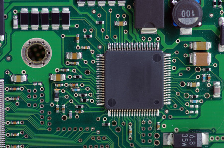
Resources for electronic reverse engineering.

Reverse Engineering Process

Step 1: Take photos and part number of the parts from various perspective. If dimension of the part (Size, Length, Pitch) is important, record down the dimension and take photos together with a ruler or a measuring tape. Recognising the footprint of the components can help identify the component.

Step 2: Label and list all the components with a designator ID for all the individual components. Consolidate the quantity.

Step 3: Label all contact point on the individual component. Tabulate a list of connection points to map the connections.

Step 4: Source for the components’ part-number, manufacturer, distributor (where to buy) and the price.

Marking Code References

SOT23 Marking Code

Check out the SOT23 Marking Code here.
Footprint similar to SOT23-3 (pitch 1.9mm) but smaller in size are
SC-70-3 (1.3mm), SOT323 (1.3mm), SOT416 (1mm)

Diode Marking Code

Check out the Diode Marking Code here.

National Semiconductor IC chip marking convention

http://www.ti.com/lit/an/snoa039c/snoa039c.pdf

SMD-CODES Databook

Active SMD Components

Marking Codes, Marking Style, Characteristics Pinout

http://www.go-gddq.com/down/2014-04/14040108467284.pdf

https://www.sos.sk/pdf/SMD_Catalog.pdf


Find out component’s standard footprint

Click here for the list of component footprints for identifying unknown components on your circuit board..

Reference Designator on PCB board

https://en.wikipedia.org/wiki/Reference_designator

Others

http://www.siongboon.com/projects/2013-09-22_reverse_engineering/

Electronic Reverse Engineering Service

PIC-CONTROL provide electronic reverse engineering service for our business clients. Check out our electronic reverse engineering service on our website or contact us for further information.

Diode Marking Code

Diode comes with many varieties. The following presents the marking code for common SMD component for 2 pins diode component.

Warning Note: Please ensure the context of the component used in the electronic design is correct. It is possible to misinterpret the part with same marking code. This marking code reference guide is meant for your convenient. Always check the datasheet to confirm if your marking code matches the part number.

Diode Marking Code (Commonly Used SMD Diode Component List)

Marking Code Package Part Number Alternative Part Number Description
M7 SMA-J 1N4007 UF1010 power diode, 1A 1000V
S3M SMC (DO-214AB)     power diode, 3A 1000V
S3X SMC (DO-214AB) BY1800   power diode, 3A 1800V
S3Y SMC (DO-214AB) BY1800   power diode, 3A 2000V
SS14 SOD-123 1N5819 CMPSH1-4 schottky barrier diode, 1A
SS16 SMA      
SS34   1N5822 CMSH3-40MA schottky barrier diode, 3A
A6   BAS316, BAS16    
A7 SOT23-3 BAV99    
A4 SOT23-3 BAV70   A4W (from China)
UM 13 SMA SMAJ440    
AC32 or (ES1D)   ES1D    
WE C   SMAJ5.0CA    
MRC   1SMB40CAT3G    
BFR   SMCJ40(C)A    
K1   MMSZ5251   zener diode 22V
V1J   10MQ100NPbF   diode, Schottky Rectifier
514 S1G   S1G (SMA, DO-214AC)   surface mount glass passivated rectifier (Vishay General Semiconductor)
WJ C7   BZT52C15 (SOD123)   15V 5mA zener diode
A51   (Maybe) BZX84   ( Maybe) Voltage regulator diodes
V3J SMC, DO-214AB 30BQ100PbF   Schottky Rectifier, 3A
F48 SS26    SS26   Schottky Barrier Rectifier
P451L    ???   ???
DO-35 1N5264B MMSZ5264B Zener diode
DO-204AL, DO-41 SB140 1N5819 Schottky Barrier Rectifier
GS1M SMA, DO-214AC     Glass Passivated Rectifier
A20 SMB SMBYW02-200   High Efficiency Fast Recovery Rectifier Diodes
         
E1 SOD-523F 1N4148WT   Small Signal, Fast Switch
E2 SOD-523F 1N4448WT   Small Signal, Fast Switch
E3 SOD-523F 1N914BWT   Small Signal, Fast Switch
E7 SOD323 RBS18V   E7 bi-directional zener diodes
         
SMCJ440CA
440A 5GGHC
SMC 1.5KE GJM 8A1K2 TVS Diode

Electronic Reverse Engineering Service

PIC-CONTROL provide electronic reverse engineering service for our business clients. Check out our electronic reverse engineering service on our website or contact us for further information.

Please also visit the main resource page for other electronic reverse engineering resources.

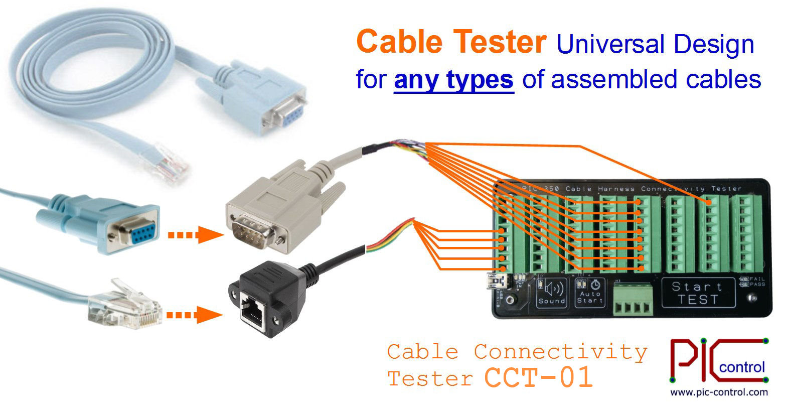
Click here to buy Cable Tester CCT-01

SOT23 Marking Code

SOT23 is commonly known for a 3 pins SMD package and is also known as SOT23-3. There is also 5 pins package (SOT23-5), and 6 pins package (SOT23-6). The SOT package is small and normally the full part number cannot be printed on the chip itself. Normally the part number is represented by a marking code printed on top of the SOT23 package.

The follows presents some of the SOT23 components marking code, which is useful for reverse engineering use.

Warning Note: Please ensure the context of the component used in the electronic design is correct. It is possible to misinterpret the part with same marking code. This marking code reference guide is meant for your convenient. Always check the datasheet to confirm if your marking code matches the part number.

SOT23-3 Marking Code

Marking Code Package Part Number Description
6B, 6B, 6C, 6D SOT23-3 BC817 npn
J3Y SOT23-3 M8050 npn
1D*, 1A*, 1B*, (1BW) SOT23-3 BC846, BC846A, BC846B npn
1H*, 1E*, 1F*, 1G* SOT23-3 BC847, BC847A, BC847B, BC847C npn
1K* SOT23-3 BC848B npn
1GM, 1H SOT23-3 MMBTA06L, MMBTA05L npn
J3 SOT23-3 S9013 npn
2TY SOT23-3 S8550 pnp
3BW SOT23-3 BC856B pnp
3D SOT23-3 MMBTH81 pnp, RF transistor
 3G  SOT23-3  BC857C pnp
       
704 SOT23-3 2N7002K-D n-ch
S07 SOT23-3 STS2307 p-ch
       
N76 SOT23-3 DDTD142JU diode
K7D SOT23-3 BAS70-04 diode (dual)
A1 SOT23-3 BAW56 diode (dual)
A4 SOT23-3 BAV70
or MIC803 – 31D3V
diode (dual)
or microcontroller supervisor circuit
A7 SOT23-3 BAV99 diode (dual)
B6 SOT23-3 BAT54A
BAR40AN3-0-T1-G
dual diode
L05 SOT23-3 78L05
or ZLLS500
5V voltage regulator
or Schottky barrier diode
       
65Z5 SOT23-3 LM6206N3 voltage regulator
6003 SOT23-3 MAX6003 (not sure) voltage reference
65Z5 SOT23-3 LM6206N3 3v3 regulator
WV4 57 SOT23-3  BAT54S schottky barrier diodes
ANW 51 SOT23-3 ??? ???
W29 55, W29 41 SOT23-3 ??? ???
431 SOT23-3 TL431 Adjustable precision shunt regulators
M2A SOT23-3 MMBT2222A npn
M7A SOT23-3 MMBT2907A pnp


SOT23-5 Marking Code

Marking Code Package Part Number Description
C20 SOT23-5 LMV7239 comparators
A63A SOT23-5 LM321 op-amp
A64A SOT23-5  LMH6642MF op-amp
313B SOT23-5 MCP6H01 op-amp
SRPB SOT23-5 LM27313 dc-dc
M5 (eg. M5YU) SOT23-5 24AA16, 24LC16B-IOT EEPROM 16K
=VG= SOT23-5 74LVC1G32GW, 74LVC1G32GW-Q100 2 input OR gate
LPFG (maybe the same LPFL) SOT23-5  ???  ???
VP9V  SOT23-5  ???  ???


SOT23-6 Marking Code

Marking Code Package Part Number Description
ASRAE SOT23-6 ZXMN2B03E6 n-ch
ANTAL SOT23-6 ZXM62P03E6 p-ch
JA8K, JA8R SOT23-6 TS5A3159 SPDT Analog Switch
AJxx, AJ6G, AJ03, AJ1M SOT23-6 MCP4725A0T-E/CH digital to analog converter
D771 SOT23-6  DAC7571 12-bit Digital to Analog
5ABK SOT23-6  (maybe) UM1665  DC-DC Boost Converter
58 SOT23-6 SI3458DV n-ch


Electronic Reverse Engineering Service

PIC-CONTROL provide electronic reverse engineering service for our business clients. Check out our electronic reverse engineering service on our website or contact us for further information.

Please also visit the main resource page for other electronic reverse engineering resources.

Click here to buy Cable Tester CCT-01

Temperature of Electronic Under Hot Sun

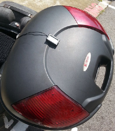
temperature under hot sunSingapore is located near the equator and the weather here is hot all year round. Electronic installed outdoor is subjected to the fierce heat of the direct sun. As a designer, you may be wondering if your electronic can withstand the high temperature for your electronic deployment in Singapore.

We have done a simple survey to measure the temperature that the electronic can be subjected to for outdoor installation in Singapore.

Temperature of Electrical Box Under the Hot Sun

For this measurement, a digital thermometer is placed inside a black plastic box. After under the hot sun (a day without any cloud) for at least over 30minutes, the temperature inside the box is recorded.

The temperature inside the enclosed box can typically go up to 40°C to 49°C in a normal environmental temperature of 30°C to 33°C.

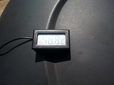
temperature inside a black plastic box reading of the temperature inside a black plastic box

reading of 48.8°C, the temperature inside this black box.


Temperature of Object Directly Under the Hot Sun

temperature under direct sun lightThe thermometer measurement probe under direct sunlight can go up to 50°C to 55°C (usually 10 to 15°C above temperature under shade).

The normal weather temperature that we always get from the weather station is a temperature of the surrounding air under a shade. No direct sunlight with the thermometer.


Designing Electronic to Operate Under the Hot Sun

Most electronic are design to operate in the range of -40°C to +85°C. For most outdoor installation, it is not too much of a problem even in a place like Singapore. For special high-temperature application, it is important to select electronic components that can withstand high temperature.


Feel free to contact PIC-CONTROL, your electronic design and manufacturing provider in Singapore.


Hyperterminal Download & Setup

Click here to Download Hyperterminal Serial Communication Program.

Hyperterminal program from WinXP is a simple program which allows connection to a serial communication port or act as a client to connect to a TCP/IP server application. A very useful communication software tools which help you debug and troubleshoot RS232, RS485, RS422, Virtual Serial COM port, Ethernet or Wifi TCP/IP UDP communication.

This program can only run on Windows Operating System (WinXP, WinVista, Win7, Win8).

Download the hyperterminal.zip (0.2MB file size), unzip and execute the program “hypertrm.exe”.

The following presents the setting up and running of the Hyperterminal software.

Alternative Terminal Program (Docklight Terminal Software)

Download Docklight Terminal Software.

Alternative Serial Monitoring Program (Serial Port Monitor)

https://www.serial-port-monitor.org/

USB Virtual Com Port Driver (for PIC-xxx USB Products)

USB virtual com port driver, CDM v2.12.28 WHQL Certified.zip

Setting Up the Hyperterminal Program

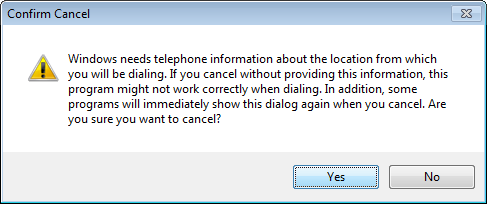
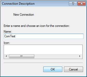
When the Hyperterminal is first started, a series of dialogue box will pop up. Follow the following procedure to skip all the dialogue box questions.

Check the box and click “No”.
Click “Cancel”.
Click “Yes”.
Click “OK”.
Enter in any name for this connection.
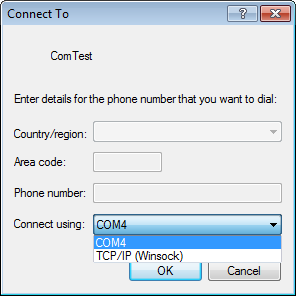
Select COM port or TCP/IP connection.

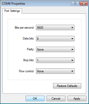
for COM Port Connection

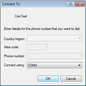
Select the COM port to use.

If you are not sure what are the COM port available on your computer system, you can go to the Device Manager to check.

For USB COM port, you can plug and unplug the connection to check which COM port is the USB being assigned to.

To go to the Device Manager  from Windows7,

  1. Click Start button on the bottom left corner of your screen.
  2. Then type “devmgmt.msc” and hit Enter key.
  3. On the program, find the entry that says “Ports (COM & LPT)” and click on the ‘+’ symbol to expand it.
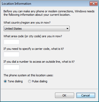
You will be brought to this screen to set up the serial port setting. Configure your serial com port accordingly.

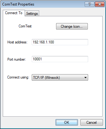
for TCP/IP Connection

For TCP/IP connection, enter in the server IP address and port number that you wish to connect to.

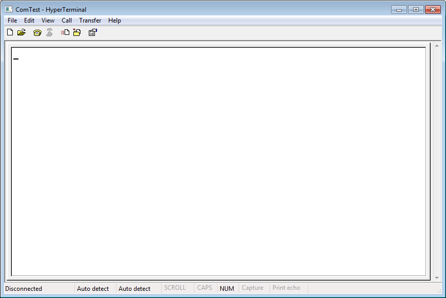
Console Screen

Terminal console screen.
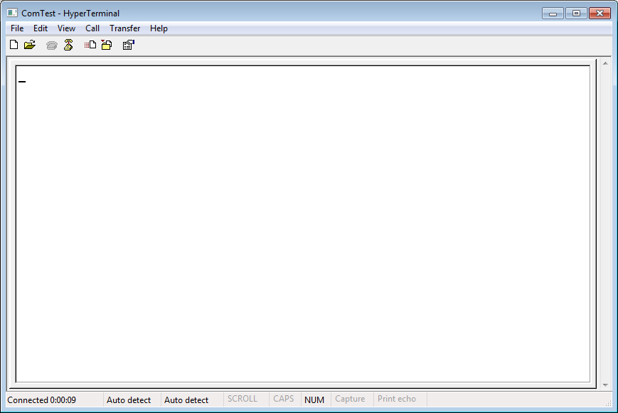
Click on the “Call” icon to start the connection.Click on the “Disconnect” to end the connection.You can see the current connection status from the bottom left of the terminal window.
Any keystroke key into this terminal will be sent over to the connected device.Any data received from the connected device will be shown on this terminal screen.
Instruction for PIC-CONTROL customer. For most PIC-CONTROL serial (RS232, RS485, RS422) or network (Ethernet, WiFi) communication product, you can press the “ESC” key. There will be response messages from the controller, indicating that the controller’s communication is working fine.

For commands to control the electronic controller, please refer to the respective products.

Running the Hyperterminal Program

Use your keyboard to key in the command on the console screen. Any reply from the controller will be reflected on the console screen.

Keystroke for Non-Ascii Character Code

Data Byte Send Keystroke
0x03 Ctrl+C
0x08 Backspace
0x09 TAB
0x1B ESC
0x0D 0x0A Enter

Electronic Component Distributors

Looking for Electronic Component Distributors in Singapore. You have dropped into the right place. We have set up this pages to update you the various means of sourcing and buying your electronic component in Singapore.

Bookmark this page now on your web-browser, so that you will always have access to this latest electronic component distributors list update for your future electronic component sourcing.

The following references provide a good source of information to get your electronic component supplies.

Buying Electronic Components Online

Sourcing and purchasing electronic component online is getting more and more popular compared to the other modes of purchase.

Most online shopping portal offer database searching portal, which enables you to do detail searching of the exact electronic component that you are looking for. A picture of the product and its detail specification datasheet is usually available so that you can browse through the details with ease and make the instant decision to purchase.

For low quantity purchase of electronic parts for your electronic prototyping use, the online store usually offers a good wide variety of choices, with shipping delivery from various part of the world.

A simple, easy and fast way to make your electronic components online. Highly recommended.

Check out the various website that you can buy electronic components online.

Retail Shopping for your Precise Electronic Components

The experience of shopping for your electronic components in the retail shops is quite different from online shopping. The fun part is that you get to touch and feel the electronic.

You want to build an electronic project but do not have an idea what the exact electronic component (switches, connectors, enclosure, wires, etc…) will be. Shop around and look out for the suitable electronic part for your project. You will never know, something exciting is coming your way. That’s how fun shopping is.

For electronic newbies who have the interest in pursuing electronic design/prototyping, physical retail shopping is your learning playground. It provides you with an instant view of the electronic world. You can also get to discover new components that you never knew it exists. Shopping helps you to expand your electronic knowledge and practical experience beyond your textbook theory.

For experienced electronic design professionals, physical shopping enables you to keep yourself updated with the electronic industries trends. Looking out for the latest components or a new method of designing electronics. Continuous updating yourself with the latest electronic trend.

Check out the places you can visit to shop for your electronic components locally in Singapore.

Electronic Components Supplier & Support

For manufacturing industrial purchase, electronic component distributors and suppliers are your best partner and support.

Local electronic supplier provides support and logistic planning for your bulk electronic purchase. They also offer a more attractive pricing for your electronic production needs.

Singapore is a multinational electronic marketplace. Many reliable brand electronic component distribution can be found locally.

Check out the list of local electronic component distributors and suppliers in Singapore.

Electronic Engineering Service

PIC-CONTROL provide electronic engineering services for our customers. We provide electronic product design, electronic product production, firmware microcontroller programming, Java application software development. PIC-CONTROL also sells in-house electronic product and solution.

Brought to you and supported by PIC-CONTROL Pte. Ltd.
Your Best Electronic Solution Provider in Singapore.

Electronic Component Suppliers in Singapore

Electronic Component Suppliers in Singapore

Looking for electronic component suppliers in Singapore for your electronic production. Check out the following suppliers and distributors.

General Component Distributors

Brand Component Distributors

Other Electronic Product and Solution in Singapore

Check out our Electronic Component Distributor page for other sources of electronic component purchase.

Brought to you and supported by PIC-CONTROL Pte. Ltd.
Your Best Electronic Solution Provider in Singapore.


Update

Appreciate your update to us using the form below, if the listed information above is found to be outdated.

[contact-form-7 id=”1042″ title=”Contact Form (Feedback)”]