Electronic Components Market and PCB Manufacturers in Malaysia | near Singapore

Electronic Parts, Market Place in Malaysia

What can we buy or shop for electronic parts, components, PCB fabrication or electronic design services in Malaysia?

For electronic parts sourcing in Malaysia, the Central Market Kuala Lumpur (also known as Pasar Seni) is a heaven place for electronic shopping. It is located in the city of Malaysia, Kuala Lumpur. There is a whole row of shops selling electronic stuff, and designing electronic projects. The shops can be found along the Jalan Pasar road which is near the Pudu Wet Market.

On this street, you will be able to find a lot of electronic parts and components. This is equivalent to the electronic components market at Sim Lim Tower located in Singapore.

Check out more from this link of the map for electronic components, parts, design or PCB from the entire Malaysia.

Komponen Elektronik Shops in Kuala Lumpur along Jalan Pasar Street, Malaysia

Jalan Pasar. A street full of electronic component shops in KL Malaysia. A 5 minutes walk from the nearest MRT train station “Pudu“.

The market opens at about 9am, and starts to close at about 5pm (from Monday to Sunday)

Electronic Components Shops near Kuala Lumpur

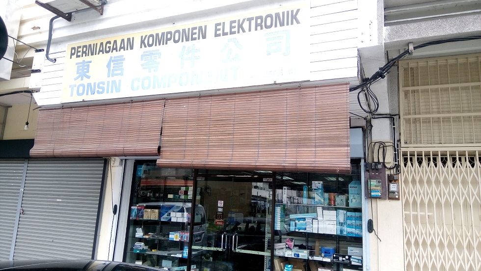
Electronic Component Shops in Penang Malaysia

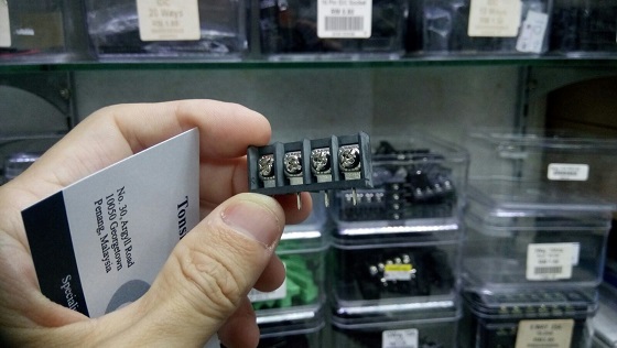
Tonsin Component in Penang Malaysia (George Town Area)     Tonsin in Penang Malaysia near George Town area

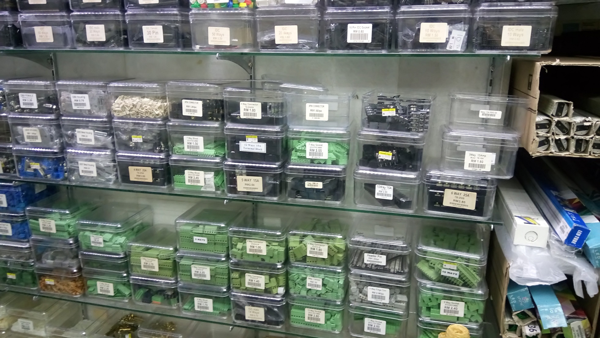
electronic component barrier terminal in Penang Malaysia      Electronic components in Tonsin shop

Electronic Component Online Store in Malaysia

https://www.cytron.io/

http://www.astanadigital.com/

https://www.autobotic.com.my/

Electronic and PCB Manufacturer in Malaysia Johor

There are a number PCB manufacturers in Malaysia Johor, which is very near Singapore. The following PCB manufacturer can also be located using the google map above.

More PCB Manufacturer in Malaysia

The following are more other PCB manufacturers in Malaysia (away from Johor)

Electronic Engineering Services in Malaysia

Looking for Electronic Design and Engineering Services in Malaysia?

Click here for a list of electronic circuit design companies in Malaysia.

Updates

Please feel free to update us for new electronic related goods and services in Malaysia. We will like to share with people more on the electronic industry in Malaysia. Hear from you. Thank you.

If you are looking for electronic parts or components in Singapore, click here check out our other web page.

If you prefer online sourcing of electronic parts, check out these online websites.

Cathodic Protection

Cathodic protection is a popular maintenance prevention measures to protect the metal steel structure from corrosion from the harsh environment. This is especially in the marine industries where metal structures close to the sea water are prone to corrosion.

The cathodic protection system is very commonly used by the shipping industry in Singapore and Malaysia. They are deployed on large steel structure to prevent corrosion. Applied to the ship or yacht’s hull to protect against marine growth.

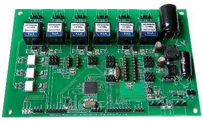
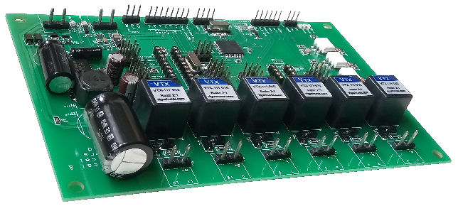
cathodic protection driver electronic circuit board

Besides cathodic protection, there are also other protection system and technology. Other methods to protect and maintenance metal steel are:

  • Maintenance painting or resist coating on the metal to isolate it from the harsh environment.
  • Apply of corrosion inhibitors to the metal.
  • Chemical dosing the pH of the environment.
  • Using a more corrosion resistant material.

The cathodic protection system is a technology that works by conducting the metal steel structure (making the metal steel structure to be protected as a cathode) and an anode with a controlled AC power. The voltage waveform is generated from a station and is conducted onto various isolated metal steel pipelines or metal structures.

Application

  • Protect metal steel pipes and storage tanks from corrosion.
  • Marine growth prevention on ship’s hull.
  • Protect equipment.
  • Underground metal pipelines protection.
  • Shielding of buried or submerged metal structure.

Products

Cathodic protection products from
Eastern Electrical Mechanical Engineers Pte. Ltd. logo Eastern Electrical Mechanical Engineers Pte. Ltd. (EEME)

cathodic protection driver electronic circuit board

Cathodic Protection Solution Service Provider

Eastern Electrical Mechanical Engineers Pte. Ltd. logo

Eastern Electrical Mechanical Engineers (EEME) is a company providing cathodic protection solution, supplies and manufacture cathodic protection products.

EEME has been delivering electrical system and cathodic protection solution to customer in South East Asia (Singapore, Malaysia, Indonesia, Thailand, Brunei), India, United Kingdom, Canada and Brazil.

Contact Eastern Electrical Mechanical Engineers for your cathodic protection solution.

Related reference:


Social Group and Resources – for Electronic, Programming and Mechanical Engineering Stuffs

Forum Discussion for Electronic Engineering

Facebook Social Group for Electronics & Technologies

Facebook 3D Printing Community

Computing Community

New Forum or Social Community in Singapore?

Appreciate your sharing on any new forum or social community relating to electronic engineering in Singapore.

Contact us so that we can update and share to attract more people into the community.


Please give us a strong support and encouragement with your good rating review .

Thank you.

Mechanical Material Engineering Services in Singapore

The following are some of the mechanical material and service providers in Singapore. Metal materials like stainless steel, copper, steel, etc… Engineering plastic is also a very common material used in the industries.

Metal Material Sheet/ Wire/ Profile

Metal Material

  • Stainless Steel
  • Copper coil, sheet, rod, bar, tube
  • Aluminum
  • Brass
  • Bronze
  • Cast Iron
  • Ferrous Metal
  • Lead

Available from:

Engineering Plastic Material Sheet/ Blocks/ Rods

Engineering Plastic Material

  • Derlin (POM, POLYOXYMETHYLENE), Anti-static/Conductive
  • Nylon (PA6)
  • Teflon ( PTFE, POLYTETRAFLUOROETHYLENE)
  • Acrylic sheets or rods
  • PC (POLYCARBONATE)
  • PVC (POLYVINYL CHLORIDE)
  • PP (POLYPROPYLENE)
  • PE/HDPE/UHMWPE (POLYETHYLENE)
  • PU (POLYURETHANE)
  • Vespel (high temperature)

Available from:

Acrylic Available from:

Plating and Treatment

Plating Process

  • Zinc Plating
  • Nickel Plating
  • Anodizing
  • Gold Plating
  • Silver Plating
  • Copper Plating
  • Electroless Nickel Plating
  • Tin Plating (Bright/Dull)
  • Electrolytic Copper
  • Electrolytic Nickel
  • Hard Chrome Plating
  • Alkaline Etching
  • Acid Etching
  • Chemical Polishing
  • Electro Polishing
  • Passivation
  • Phosphating
  • EN Teflon
  • Cadmium Plating
  • Chromate Conversion Plating
  • Blueing

Heat Treatment Process

  • Hardening & Tempering
  • Homogenize / Solution Treatment
  • Precipitation Hardening / Ageing
  • Magnetic Annealing (Bright)
  • Stress Relieving / Normalising / Annealing
  • Hydrogen-gas cleaning / Degassing
  • Baking / Sintering / Stabilization

Available from:

Others

You may also like to check out this other mechanical engineering prototyping services and resources or mechanical screws supplier in Singapore.

Loading Arduino Bootloader to brand new ATMEL Microcontroller

This article is written as a guide to loading an Arduino bootloader or firmware onto a brand new ATMEL microcontroller IC chip.

When you first purchase a legitimate ATMEL ATMEGA16U2 chip, it is actually loaded with a default DFU firmware. If you did not purchase the microcontroller from the legitimate source, there might not be any firmware pre-loaded inside. In this case, you can only load the bootloader firmware using the ATMEL ICSP programmer method.

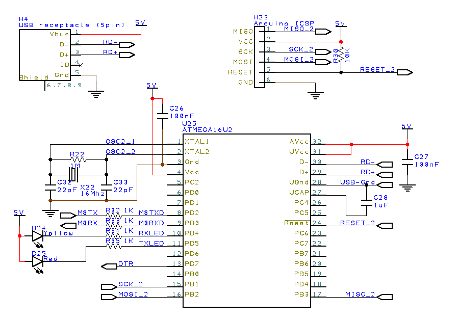
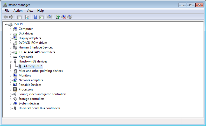
If you built the basic USB circuit using the ATMEL microcontroller and plugged it into your computer’s Windows Operating System (example Win7), you should be able to see a USB device name “ATmega16U2” under a folder libusb-win32 devices in the Win7 Device Manager.

Basic USB circuit for ATMEGA16U2

Basic USB circuit using ATMEGA16U2 microcontroller from AMTEL.Click to enlarge the basic USB ATMEGA16U2 schematic circuit.

Using the ATMEL FLIP software, you will be able to load firmware or bootloader using its default ATMEL DFU bootloader. You can download this FLIP software from ATMEL website. Or you can download here,

Uploading Arduino USB Serial Firmware via FLIP

  1. Plug the USB circuit to your computer. You should see the ATmega16U2 device in the Win7 Device Manager. This is the default DFU firmware loaded in the ATMEGA16U2 microcontroller chip. It is also known as the DFU mode.
    ATmega16U2 in Device Manager
  2. Install and execute ATMEL FLIP software.
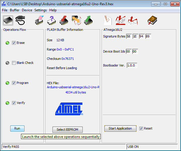
  3. Select the microcontroller. Click “Device”>”Select…”, or use the shortcut key <Ctrl>+S. Select the microcontroller “ATMEGA16U2”.
  4. Select the communication. Click “Settings”>”Communication”>”USB”, or use the shortcut key <Ctrl>+U.
  5. A dialogue box may appear. Then click open.
  6. Download this USB serial firmware for ATMEGA16U2. For ATMEGA8U2, you can download the USB serial firmware here.
  7. Load the firmware on the FLIP software. Click “File”>”Load HEX File…”>”Arduino-usbserial-atmega16u2-Uno-Rev3.hex”
  8. Ensure the check box is checked. “Erase”, “Program” and “Verify”
    ATMEL FLIP software interface loading Arduino USB serial firmware to ATMEGA16U2
  9. Click “Run”.
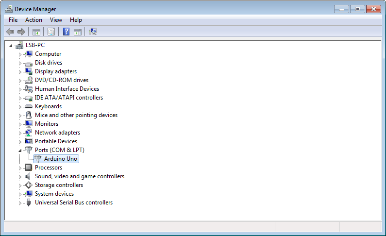
  10. Once the firmware is loaded, you can unplug the USB connection and plugged it back to your computer. You should be able to see in your device manager as “Arduino Uno” under the section “Ports (COM & LPT)” instead of the previous “ATMEGA16U2” device.
    Arduino UNO ini Device Manager
  11. The ATMEGA16U2 is now loaded with the USB serial firmware which is used in a typical Arduino UNO board. Your ATMEGA16U2 microcontroller is now a USB serial (CDC) or USB to serial communication converter. The same converter IC chip used in Arduino UNO board.

Upload DFU Bootloader to brand new ATMEL USB Microcontroller

For the ATMEL microcontroller which does not have the default DFU firmware pre-load into it, you can load the following DFU hex file for the respective ATMEL microcontroller chip.

Since the microcontroller does not have a bootloader, the only way to load this DFU to the microcontroller via an ATMEL ICSP programmer. The instruction guide for the uploading of a firmware using an ICSP programmer can be found here.

Upload Arduino Bootloader into ATMEGA328P Microcontroller

For the ATMEL Microcontroller ATMEGA328P used in Arduino UNO, the Arduino bootloader can be upload using an Arduino ICSP programmer with the Arduino IDE (integrated development environment) Software.

  • Run the Arduino IDE software.
  • Select “Arduino UNO” from the Tools > Board menu.
  • Select “ArduinoISP” from Tools > Programmer (depending on the programmer that you are using)
  • Run Tools > Burn Bootloader

Now your ATMEGA328P microcontroller is loaded with the Arduino bootloader firmware.

Take Note for ATMEGA328 Microcontroller

Uploading of  bootloader for ATMEGA328 (signature ID 0x1e 0x95 0x14)  is different from ATMEGA328P (signature ID 0x1e 0x95 0x0F).

Check out the following webpage if you want to upload the bootloader to ATMEGA328.

Other Arduino Related Services

Mechanical Prototyping Resources

Mechanical design and manufacturing companies providing mechanical part fabrication and prototyping in Singapore. CNC machining.

Mechanical Design Companies in Singapore

The following companies provide high end mechanical enclosure design in Singapore. If you are looking for designing enclosure for your mass production purpose, check out these design companies in Singapore.

Mechanical Prototyping Companies in Singapore

Laser Cutting and laser marking service companies in Singapore

Laser Cut for Stainless Steel Sheet Metal

Silkscreen Printing Service in Singapore

Stencil

Workshop

Others

You may also like to check out this mechanical material engineering services and resources or mechanical screws supplier in Singapore.

Click here for electronic product prototyping and development services in Singapore.

Serial Communication Standard Protocol

Most of the standard is a derivative of a formal mature technology. The following introduces the serial communication the is commonly used in the industries. Most of them are fairly similar but are known as a different name.

Common Physical Communication Layer

  • UART (0-5V, 0-3.3V)
  • RS232
  • RS485, RS422
  • Ethernet
  • USB
  • KNX/EIB
  • LIN (for automotive single wire)

Other Physical Communication Layer

  • RF

Protocol Layer on the common Physical Layer

Protocol layer is the data byte format design for a certain method of communicating. The protocol layer make use of the physical layer to send the data over a communication channel.

The following are some

  • Modbus (uses RS485, RS232 or Ethernet)
  • CAN bus (uses RS485)
  • MDB, Multi Drop Bus protocol (uses 9 bits RS232/RS485)
  • Multi-Master Bus

Other Protocol Layer

  • WiFi
  • Zigbee
  • Xbee
  • Zwave
  • Bluetooth

Electrical Noise & Interference Problem

Having problem with your electronic equipment because of a electrical noise interference?

Electrical Noise

Electrical noise due to switch on the power line.

Suppressed Electrical Noise

Suppressed electrical noise on the 230Vac power line

You switch on your fan across your room. Your TV gets the disturb, then starts to flicker or blank out for a short pulse of time. Your mobile is receiving an incoming call and your audio speaker starts to give out weird sounds. These are a few of the common electrical interference that we usually encounter daily from our digital devices and appliances.

Electrical noise is very common in any electrical appliance or electronic devices. It is always there, but we can’t see it with our eyes nor we can hear it with our ears. But we can learn more about electrical noise and prevent them from affecting our equipment system, the way we want them to operate.

In this article, we will focus solely on the most commonly encountered switching noise and how we can prevent them.

For consultation enquiries, feel free to contact PIC-CONTROL for electrical or electronic troubleshooting services in Singapore

What is an Electrical Noise?

Most people, even a trained person tends to perceive “Noise” as a single entity. When an electrical problem occurred, blame is typical pushed to an entity known as “THE NOISE”. In reality, the electrical noise that is affecting your electrical or electronic appliances is simply an unwanted electrical signal which you don’t want. There is no difference between a signal and a noise in terms of the electrical properties. A signal is something desirable, something that you want, while noise is the signal that you don’t want to have.

Unwanted electrical signal (“Noise”) itself can be in many different forms. This returns to a need to understand how electrical/electronic actually works. A real world is never ideal, not perfect. It is important to understand these imperfections so that we can minimise the undesirable effect that it could bring.

Noise is something very common in our everyday electrical appliances. A common source of noise spike usually comes from the switching on/off of an inductive load. An inductive load could be a motorised fan, door bell, magnetic ballast lighting which we will be discussing here. There are also many other types of noise and sources of noise which are rare and not often encountered.

Usually, noise does not cause much of a problem. When an appliances or electronic device has low immunity to noise interference, it may be affected by the noise and results in undesirable operation. Most of the time this can be avoided through proper wiring method. If proper wiring is not a solution then you will have to add in additional noise filtering product to minimise the interference.

Intermittent failure found on electronic device or electrical appliance is very difficult to troubleshoot. Very often, it indicates that the source of the noise problem is not clearly understood yet. It is important to come up with a hypothesis about the source of noise and think of a way to reproduce the problem. If you are able to reproduce the problem consistently, you would have already solved 50% of the problem.

Electrical Interference (Type of Electrical Noise)

“Noise” may sound like an entity which people tends to perceive. People tends to relate any electrical problem to the “noise”. In practice, the word itself is an abstract name. It is actually not something easy to resolve even for a trained engineer without enough practical experience. There are many types of electrical noise interference that need to be differential through a troubleshooting process. An experienced engineer can have that instinct to detect that problem. A new engineer will have to start his own hypothesis and conduct experiments to verify his understanding of the subject (a practical learning process).

All appliances generate some sort of noises. Appliances are also subjected to be affected by noises. The type of noises and its magnitude can trigger your appliance to misbehave.

There 3 ways noise can sneak into your device or wires,

  1. Noise coming from another device connected through a shared physical wire.
  2. Noise magnetically induced from an adjacent device or wire.
  3. Noise radiated from a distanced device or wire.

Noise can simply come from anywhere to any appliances. Here, we will only discuss the commonly encountered noise that is due to the improper way of wiring the electrical infrastructure.

There are proper ways to reduce these interferences. First, we have to know where the noise comes from and how it gets into our device. Knowing it will allow you to apply the right solution to the problem. You can’t just blindly buy a surge protector or noise suppressor and expect the noise to go away. The problem can only go away if you apply for the correct medicine.

The following, we will focus on the simplest, most common noise on the power line.

Noise From Power Line

One of the most common electrical noise problems in Singapore comes from current ripples propagating from a switching inductive device. A noisy device source is usually not a significant factor which can disrupt your sensitive devices. However the electrical wiring in Singapore is often in the form of single core wire looping, it becomes easier for the noise to interfere with other devices.

For a typical home and office electrical installation, the incoming power is typically split into 2 main groups. One group for lightings and the other group for the 3 pins socket electrical mains. For a group of sockets located within a room, the code of practice for electrical installations (CP5:1998) allows multiple sockets to be looped (linked) together using a single wire from the main circuit breaker (MCB) box.

This form of looping creates a lot of disturbance for the latest low power/voltage electronic from noisy appliances.

This can be observed at times when you switched on a fan in a room and the TV located near or in the same room gets a flickering or sometimes the screen gets blank out. This may happen to radio where the sound gets chopped off.

Common Source of Electrical Noises

Switching inductive load is a source for noisy appliances. The switching of an inductive load if happened at the peak voltage can generate a significant spike of noise. Switching at the zero-crossing would be calm, with no noise generated. Some modern appliances are designed to switch at the zero-crossing which helps reduce the emission of these noises. For other appliances, it is a matter of random chance that the spike noise is generated. These can be observed at times when you switch on the lights. Sometimes, you can see an electrical spark inside the switch panel when the light is switched on. This is when the connection to the lights load near the peak of the AC power.

The following are some of the common noisy appliances.

Common Noisy Appliances (inductive)

  • AC motorised fan, or machinery
  • Magnetic ballast fluorescent lamp
  • Light
  • AC Energised Door Bell

Simple Solution to reduce Electrical Noise

There are many ways to reduce electrical noise depending on the nature of the noise. The following are 2 simple precautions you can take to reduce the chances of noise.

Use STAR connection to reduce noise

Using a star connection helps isolate a noisy line from your electronic appliances/devices.
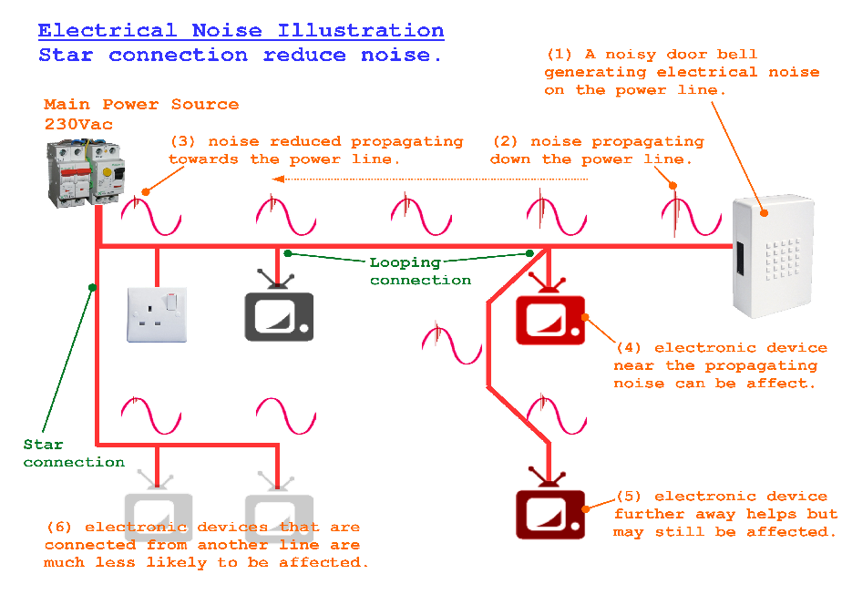
Electrical Noise reduced using a STAR connection on your power line.

Noise generated by noisy appliances like a wall switch or some door bell can propagate down towards the power line. Noise will get attenuated as it travels down. Electronic equipment or devices that are installed near the path of the noise can be affected. You can imagine the noise propagating like the wave on water. The wave will fade off when it is further away from the source.

Most electrical wiring in Singapore do looping connection to reduce the wiring cost. It makes more economical sense to tap power from the nearest power line rather than to lay another long wire from the main electrical box. There is an installation standard governing the maximum number loop that an electrician is allowed to loop.

If your electronic device is an important part of a system, it is better to have a dedicated electrical line (STAR connection) laid specially for it.

*** you can click on the images to enlarge

Use Twisted Wire to reduce noise

Noise can be coupled from one wire to another. It is important to keep data communication cables away from the noisy source as noise can be coupled and corrupt the data transmission.

Further distance can help reduce noise. Shielding of the noisy and data cable also help reduce the chances of noise coupling.

The reason why noise can be coupled to nearby wires is due to the electromagnetic property of electricity. Most people would think that the electrical power and signal is transmitted through the copper wire inside the wire’s insulator. This is only partially correct. While most of the energy is contained within the copper, there is also energy (power) flowing between the wires and around the wires. If there is a wire nearby, this energy can be coupled to it.

This is also why in most data communication cable, the data line (differential pair) is often paired up as a twisted wire. The reason for the twist is to ensure that there is a minimum gap between the two wire. A close gap means less chance of induction noise coupling out. A twisted pair wire will induce less to the outside. The opposite is true, a twisted pair wire is less influenced by external noise.
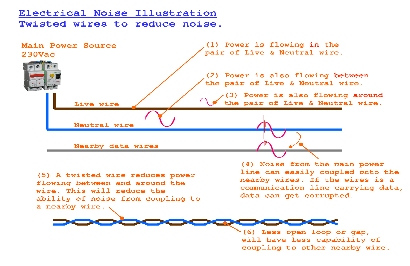
Reduce electrical noise problem using twisted wires

*** you can click on the images to enlarge

Use Noise Filter or Suppressor Products

If you have done the suggested basic noise prevention method as suggested above, you would have propably reduce the probability of failure by at least 80%.

On the market, there is a wide range of noise filter, noise suppressor, anti-noise products. These products may not necessary helps if you did not ensure the basic wiring is done properly or understood the noise problem correctly.

Structured Wiring (Smart Home Wiring)

Wiring should be grouped accordingly to the signal type.

  • High Voltage Power
  • Low Voltage Power
  • Analog Signal
  • Digital Signal
  • Communication data cable

There are standards that provide a reference guide as to how the wiring should be laid to reduce the probability of encountering a problem. They are the EIA/TIA-568 for Commercial Wiring Standard, and EIA/TIA-570B for Residential Wiring Standard.

There is a trend of installing a master switch to switch off all your appliances (non-critical). This means that when you are out and nobody is at home, you can simply switch off the master switch, instead of going room to room to search for lights and appliances to switch off. Of course, power to the security system, refrigerator and the fish tank water filtration and oxygen system, etc… should be switched on at all times.

Network points to every room from a central location is recommended. There should be a minimum of 2 network point per room. The network point can also be used for the analogue/digital telephone line point.

Wireless is also a trend. As much as possible, avoid wireless. For a new home, it is better to plan for Ethernet/Fibre network as the data communication structure. Use wireless as a solution for existing home when there is no way wire can be laid.

Electrical Noise Consultation

PIC-CONTROL provides consultation service to local businesses in Singapore if you need further help for your electrical noise problem.

The consultation fee starts from $500 (fee to be collected before the first meeting). This fee does NOT include the implementation of the solution.

Electrical Noise Suppression Filter

There are many different types of noises in an electrical system. The remove the noise, it is important to understand the type of noise that you are dealing with. Only by applying the solution to the right problem, you can eliminate or reduce your noise problem.

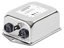
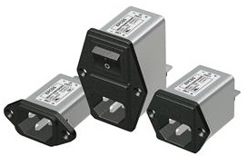
EMI Filter for 230Vac

EMI Filter for 230Vac     IEC socket with EMI EMC filter for 230Vac

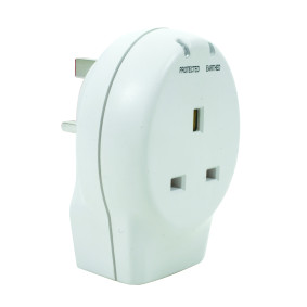
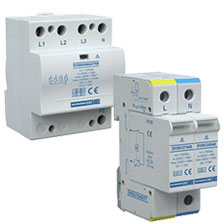
Surge Protector for Power Line

Surge protector socketSurge protection device (DIN rail mounting)

Surge protector socket and DIN rail mount from

Maplin

ROXBURGH EMC

Power Factor Compensation

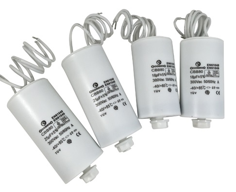
Power factor compensation capacitors.

Ferrite Bead

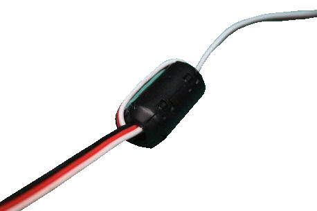
Ferrite bead EMI noise supression

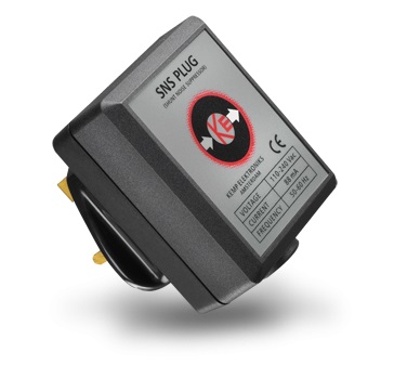
Shunt noise suppressor plug.


Microcontroller Firmware Programming Upload with ATMEL Studio

Introduction

ATMEL microcontroller is quite a popular microcontroller among the younger generation of hardware programmers due to the popularity of the Arduino IDE platform. Arduino is a higher level programming platform base on ATMEL microcontroller series. While Arduino is a very simple to use firmware programming platform for a beginner, it can be quite challenging for advanced programmer who wants absolute precision control over their software algorithm.

The popularity of Arduino results in a community of programmers sharing Arduino related information. Programmers can easily find support and resources relating to Arduino. However, the issue is that lesser programmers are now using ATMEL studio to program their ATMEL microcontroller. The resources for ATMEL studio is accurately very limited at this point in time. This is unlike the competing Microchip series microcontroller where its documentation is a lot much better than ATMEL. Now that Microchip has acquired ATMEL microcontroller business, we can expect the documentation to improve over time.

The purpose of this web page is to assist those who are new to the ATMEL Studio platform, to guide them to upload their source code (or microcontroller machine hex code) into their ATMEL microcontroller.

Things That You Need To Prepare

  1. Your ATMEL microcontroller
  2. ATMEL Studio
  3. Programmer tool for ATMEL microcontroller
  4. An adaptor board or breadboard for your microcontroller
  5. Wires for connection
  6. Firmware (a hex code file *.hex)

ATMEL Microcontroller

In this example, we are using a very simple microcontroller chip ATtiny44A from ATMEL.

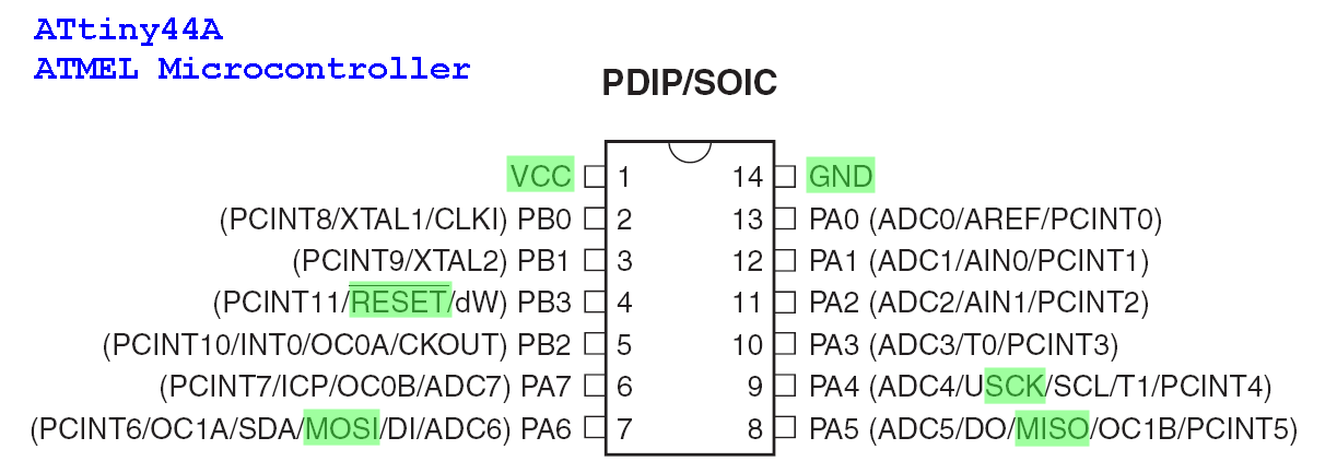
The following are the pinout for the microcontroller ATtiny44A (SOIC IC package)

ATtiny44A programming pins pinout diagram.

Please take note of the pins that are highlighted in green. These are the ISP programming pins on your microcontrollers. They will be connected to a programmer tool so that your firmware can be uploaded into the microcontroller chip.

The same 6 pins for ISP programming will be located at a different pin location for other ATMEL microcontroller chip part number. The firmware upload process is similar for other ATMEL microcontrollers part number. We just need to take note of the ISP pins of the particular ATMEL microcontroller.

The following are the ISP pins on a ATtiny44A microcontroller.

ISP Programming Pins for ATtiny44A Microcontroller

  1. MISO – Pin 08
  2. Vcc – Pin 01 (for powering up your microcontroller)
  3. SCK – Pin 09
  4. MOSI – Pin 07
  5. RESET – Pin 04
  6. Gnd – Pin 14 (for powering up your microcontroller)

The connection of these ISP pins to the programmer tools will be presented in the next few sections.

ATMEL Studio

ATMEL Studio is a free IDE (integrated development environment) software for development work on ATMEL microcontroller. You can write your firmware using C Programming or Assembly Language here, compile your source code into a *.hex code and download the *.hex code into your microcontroller through this integrated software platform.

Download the ATMEL Studio here.

Programmer Tool

A programmer tools helps you to connect your computer to your microcontroller chip. It is used for uploading the *.hex code into your microcontroller.

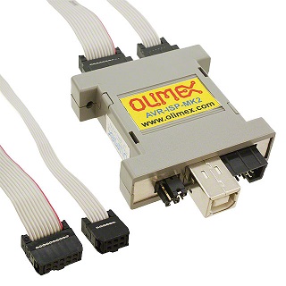
There are a number of programmer tools which allows your to upload your firmware. In this example, we are using the AVR-ISP-MK2 programming tool from OLIMEX.

Other commonly known programming tools available are ATMEL ICE and USBasp AVR.

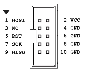
Please take note of the programmer tool pin out on their IDC connector header pins. This will be needed in the subsequent section for connection between the programmer and the microcontroller chip.

AVR-ISP-MK2 Programming Tool

Programming tool AVR-ISP-MK2

Can be used for both ATMEL Studio or Arduino IDE, but need to change firmware which is very troublesome and problematic.

AVR-ISP-MK2 programmer pin out.

ISP pin out (IDC 10 pins)

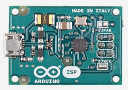
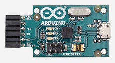
Arduino ISP Programming Tool

For illustration only. Not for use with ATMEL Studio.

Used for Arduino IDE

Arduino ISP programming tool.     Arduino USB 2 Serial Micro programming tool

Arduino ISP programmer pin out. (Arduino ICSP pinout)

Arduino ISP pin out (IDC 06 pins)

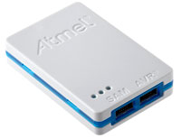
ATMEL ICE Programming Tool

Programming tool ATMEL ICE

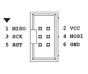
ATMEL ICE programmer pin out.

ISP pin out (IDC 10 pins)

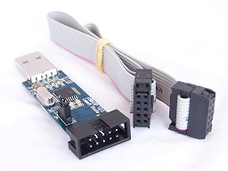
USBasp AVR Programmer

USBasp AVR programmer tool

USBasp AVR programmer pin out.

ISP pin out (IDC 10 pins)

Adaptor for Microcontroller IC Chip

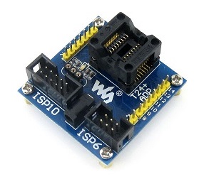
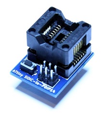
Most microcontroller chip nowadays are commonly in a surface mount package. The SMD package for ATtiny44A microcontroller is SOIC14. In order to program this SOIC14 chip, an adaptor may be needed. The following are some adaptor that you can purchase for your firmware programming.

If your circuit design has already incorporate the ISP programming pins into your PCB layout design, then you do not need to use programming adaptor socket. You just need to solder the microcontroller directly into your PCB board and download your firmware via the onboard dedicated ISP pins using an ISP programmer.

Programming adaptor socket (SOIC14) for ATtiny44A microcontroller.

Purchase this programming adaptor test socket (SOIC14) for ATtiny44A microcontroller from dhgate.com.

Programming adaptor socket (SOIC14) for ATtiny microcontroller.

Purchase this programming adaptor test socket (SOIC14) for ATtiny microcontroller from tindie.

Wires Connection

In order for the firmware (*.hex code) to be uploaded to your microcontroller you will need to connect the ISP programmer pins to the respective pins on your microcontroller.

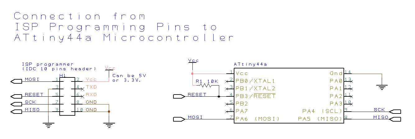
The following is a simple schematic to connect the ISP programming pins (IDC 10 pins header) to the ATtiny44A microcontroller.

ISP Programming Pins to ATtiny44A microcontroller connection.

Please note that you will need a pull-up resistor of about 10KΩ between the VCC and the RESET pins.

The following section will be using the ATMEL Studio software to help us check if our hardware connection is done correctly.

Firmware

In this instruction guide, we assume that you already have a *.hex firmware available for uploading into the ATtiny44A microcontroller.

A *.hex file is generated after your project is compiled and built from your C Programming or Assembly language source code.

Device Programming

ATtiny44A device programming in ATMEL Studio.

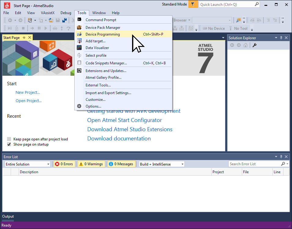
1) Atmel Studio IDE Software

Open up the Atmel Studio IDE (Integrated Development Environment) software.

To upload a firmware to the microcontroller, open the Device Programming tools.

Under the AtmelStudio’s menu, select the menu “Tools”->”Device Programming”.

ATMEL microcontroller device programming setup

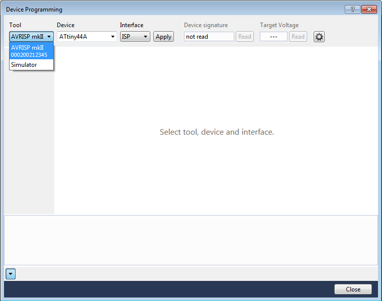
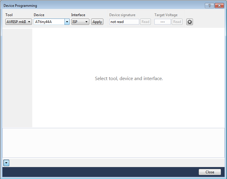
2) Device Programming Dialog

A dialog box will pops up like the one on the left.

Under the “Tool” section, select the programming tools that you got for your ATMEL microcontroller.

In this example, we are using the AVR-ISP-MK2 programmer tool from OLIMEX, so we have selected AVRISP mkII.

3) Selecting Your Programmer

Please ensure that your USB programmer tool is plugged to your computer. If you did not connect it to your computer, it will not appear in this “Tool” section. If you plugged in the tool, the name of the tool should reflect immediately (real-time) on this drop down menu. The name will be removed immediately when you unplug out your tool.

If your programmer tool is not listed in this dialog box, it could be the device is not installed correctly, or a wrong driver is installed. In this case, you may have to go back to your ATMEL programmer tool supplier for further assistance.

Always refer back to your programmer tool’s provider for the setting up of the tool. Different programmer tool may have a different configuration that is needed to be set up before it can upload firmware into your microcontroller chip successfully.

4) Select Your Microcontroller

Next. Under the “Device” drop down box, select the device “ATtiny44A” which is the microcontroller which you will be uploading the firmware to.

Keep the options “ISP” under the “Interface” menu.

Once this is done, click on the button “Apply”.

If your connection between your ISP programmer and your microcontroller is done correct, you will see a 6 digit hex code under the menu “Device signature”. In our example, we are using the ATtiny44A microcontroller. If the connection between your programmer and the ATtiny44A microcontroller is correct, you will see the text “0x1E9207” for the device signature. This is a unique ID for an ATtiny44A microcontroller.

If an error message appeared after clicking on the button “Apply”, it means that there is probably a problem with the connection. Check to confirm if the connection is wired correctly. Check if the wire is broken or if there is any wire shorted to another line. You will also need to ensure that there is a Vcc voltage of 5.0V or 3.3V on your microcontroller pin 1 and pin 14. If the microcontroller is not supplied with power, the same error message may appear as well.

Microcontroller Device Programming in Atmel Studio

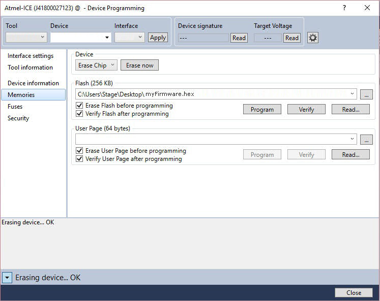
5) Upload Your Firmware to the Microcontroller

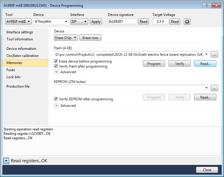
On the left-hand side of the list, select the option “Memories”. The right side of the Device Programming window will be similar to this screenshot.

Under the Flash section, click on the button “…” to select the firmware file (*.hex) from your computer system that you want to upload to your microcontroller. In this example, we are loading a filename “myFirmware.hex”.

You should check the box for the options as in this screenshot example. These settings are typical, though not very important if you forgot to select.

Click on the button “Program”. You should start to see a series of messages near the bottom of the dialog box’s screen.

The following is probably what you will see,

Erasing device… OK

Programming Flash… OK

Verifying Flash… OK


These messages indicate that your firmware is successfully uploaded into your microcontroller. You can disconnect the programmer or power off to remove the chip for further testing or use it for your production.

If an error message is encountered, repeat the checking procedure again as mentioned earlier to ensure that the programmer tool is connected correctly to your microcontroller.

Lock and Protect the firmware for ATMEL Microcontroller

There will be times you will want to prevent others from copying your source code out from your microcontroller. Most of the microcontroller have code protection bits which you can enable. Once the code protection bits are enabled, the code will not be able to be read from the microcontroller.

You will still be able to overwrite the microcontroller with new codes. After loading in the new codes, you will need to re-enable the protection bits again to lock your codes.

reading firmware from Atmel microcontroller ATTINY44A

1) Reading from a Normal Microcontroller

Open up the “Device Programming” dialog box from the ATMEL Studio IDE. Assuming you have just upload your firmware onto the microcontroller. We are now going to read the machine code from the microcontroller.

Connect up your programmers to your microcontroller as usual. Go to the section on “Memories”, the same section where you upload your firmware to the microcontroller.

To read from the microcontroller, click on the button “Read”.

A dialog box will appear asking you for a new file name for this read file. For this example we name the file as “Document.hex”, then click Ok.

The programmer will proceed to read the microcontroller and save the machine codes onto the file “Document.hex”

valid firmware codes read from an Atmel microcontroller

2) Code Read Result from a Normal Microcontroller

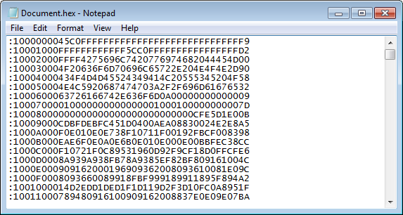
In this section, we will open the read file to have an idea how the machine codes for the microcontroller look like.

Open the saved file “Document.hex” using the Notepad.exe or other text viewer application on your computer system.

You should be able to see a long list of hex numbers similar to this example shown on the left.

You don’t have to know anything about the code. Just remember that they looks like a random chunck of numbers/letters inside the file.

code protect for Atmel Chip ATTINY44A

3) Set Code Protection to the Microcontroller

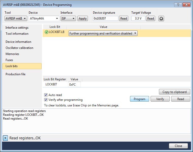
Next step, we are going to set a protection on the microcontroller to prevent others from reading the machine code. Proceed to the section on “Lock bits” as illustrated on the left.

Above the button “Copy to clipboard”, there is a field name “LOCKBIT”. On the right side is a text box where you can key in a value.

The default value may be 0xFF. Change that to 0xFC. 0xFC is the settings of LOCKBIT for the locking of the program’s memory inside the ATMEL44A microcontroller. The details can be found on section 19.1, pg 159 of the ATmega44a datasheet. Please note that 0xFC only works for ATMEL44A microcontroller. For other ATMEL microcontroller, this LOCKBIT code may be different. You will have to read the datasheet for the correct settings.

After changing the value to 0xFC, click on the button “Program” so that the programmer can apply this code lock setting onto the microcontroller.

There will be a series of messages which indicates that the setting is done successfully.

Starting operation write registers
Writing register LOCKBIT…OK
Write registers…OK
Starting operation verify registers
Verify register LOCKBIT…OK
Verify registers … OK

Your microcontroller is now code protected. Next, we will have to verify if we are still able to read the machine code from the protected microcontroller.

reading firmware from Atmel microcontroller ATTINY44A

4) Read Firmware from a Code Protected Microcontroller

This is the same process that we did previously to read out the machine code.

Go to the section “Memories” and click on the button “Read” and save the read machine code in a file.

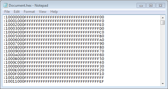
blank codes read from a code protected ATMEL microcontroller

5) Code Read Result from a Normal Microcontroller

Now that the machine code is read, open up the file to have a look at the read machine code again.

It should look different from the previous read attempt. As illustrated in the left side, you should notice a lot of “F” instead of the random chunk of numbers/letters.

This indicates that the programmer fails to read out the machine code from the microcontroller. You cannot read it because the microcontroller was locked by you.

There is no way to unlock it. You can erase the memory from the microcontroller or overwrite the microcontroller with a new firmware (machine codes).

Please note that when you overwrite the microcontroller with a new firmware, the microcontroller may not be in the lock mode. To ensure your code is protected, you can proceed to the “Lock bits” to do the code protection again.

That ends the instruction for protecting your firmware on an ATMEL microcontroller chip.

C Programming, Compile and Upload Firmware

For C programming. You can open up your project files, and start editing your program, making the necessary changes. After this is done, you can press the button “F5” on your keyboard. The ATMEL Studio will compile the project, generate the *.hex file and upload the updated firmware to your microcontroller in a single step.

If you encountered errors during the compilation process, you will need to correct it and recompile again. There will be no firmware uploaded if your C programming source code contains error.