Rain Sensor Awning Controller

This is a timer clock awning controller for rain sensor application.

This awning will automated lower down the awning when rain is detected. A timer is available for you to set the operation timing through the week.
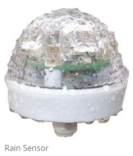
User Operation Introduction
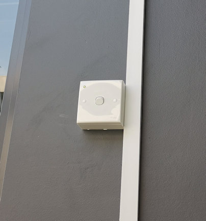
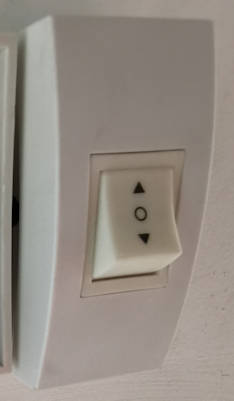
Rain sensor switch with a green LED indicator.
Awning manual control switch

Rain Sensor Switch

This switch on the wall enables user to switch the rain sensing function On/Off.

There is a green LED indicator on this switch. If there is no light on this indicator, it means that the sensing function is not in operation.

A green light on the indicator means that the rain sensing function is enable. A blinking green light indicates rain sensing enable and rain is detected.

If the rain sensing function is enable, the controller will open up the awning when rain is detected.

If the sensing function is disable or when there is no rain detected, the controller allows user to control the awning manually via the awning switches on the wall.

Rain Controller Description

There is a timer on the controller which allows you to set the non-operating hours of the system. Awning can be programmed to retract itself when it is off operating hour. This ensure that the possibility of damage to the awning can be minimise during windy days. When not in operation the controller will roll up the awning to keep the awning properly intact. You may also add your own wind speed sensor to signal the awning to roll up when heavy wind is detected.
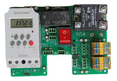
Features

  1. Auto draw down awning when raining and pull up after rain is stopped.
  2. Allow manual awning control.
  3. Control awning/rain-sensor operation time period throughout the days of a week. Flexible timer controlled.
  4. Solid state power control of two awning.
  5. Allow installation of up to 2 sensor rain. For redundancy.
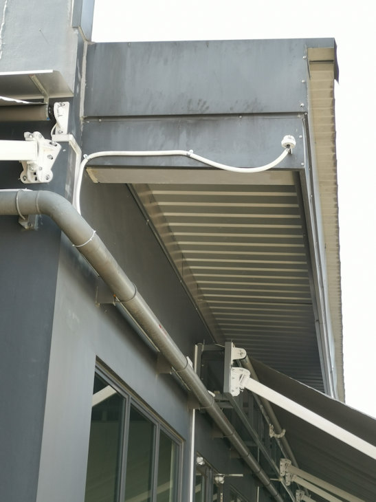
Rain sensor & Awning installation

TM-630A timer module settings

The timer module is using a standard product from SINOTIMER model TM-630A. It is used to shutdown the rain sensing system operation during the day/time of the whole week.

The operating manual can be downloaded here. (0.5Mb)
Click here to download.

The module is by default in a lock state. The keypad will not be responsive until the button panel is unlocked.
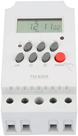
SINOTIMER model TM-630A

Unlock or Lock TM-630A timer module

  1. Press the button C/R 4 times, the lock symbol on the screen will disappeared.
  2. If left unlock for a period of time, the panel will return to the locked state.
  3. You can press the button C/R 4 times to lock the panel at any time.

Manually control the relay output of this timer module

  1. After unlocking the panel, press on the Red button (labelled Manual) to toggle the relay output, On and Off.

Setting the relay output to turn on for a specific date/time of the week

  1. After unlocking the panel, press on the button P to cycle through the programming settings.
  2. The display will cycle through 1on, 1off, 2on, 2off, 3on, 3off, …. up to 28on, 28off. This allows us to set 28 different period of timing to on/off the relay output.
  3. 1on means the first set of timing to switch On the relay. (output shorted circuit)
  4. 1off means the first set of timing to switch Off the relay. (output opened circuit)
  5. 2on 2off are the 2nd set of timing to switch the relay output on/off. You can set up to 28 sets of day/timing for the whole week.
  6. Eg. For 1on setup, press the respective button H+, M+, and D+ to set the hour/min/day/days of the week to activate the relay output.
  7. The same goes to 1off to set the time/day to deactivate the relay out.
  8. Press on the button P to cycle to the next set. This will also save your settings.
  9. You can press on the button Clock to exit the programming, and press the button C/R 4 times to lock the panel.

Setting the TM-630A module’s clock

  1. After unlocking the panel, press the button CLOCK together with the button H+ to set the clock’s hour.
  2. Press the button CLOCK together with the button M+ to set the clock’s minutes.
  3. Press the button CLOCK together with the button D+ to set the day of the week.

Controller Operation

  1. User is able to enable rain sensing mode, which will pass the rights to the sensor to controlling the awning. Disabling the rain sensing mode, allows user to manually control the awning.
  2. When user leave the system on manual mode, rolling the awning up/down can be controlled via the awning wall switches.
  3. User can manually control awning when rain sensing mode is enabled and there is no raining detected.
    When raining is detected, the system will not allow user to control the awning. The awning will automatically lower down the awning. The awning will not be rolled up. If the user want the awning to automatically roll up when the rain stopped, user can permanently leave the wall switch in the up position. When the rain stopped is detected, the control will be returned to the wall switches. Though if the wall switch is at the roll up position, the awning will proceed to roll up when the rain stops.
  4. After office hour features. This feature will force the awning to roll up after its operating hour. This is to minimise the duration of the awning opened, which minimise the chance of awning being damage by strong wind.
    When the rain sensor is enabled, the awning will be force to roll up. If it is still raining after the office hour, the system will allow the awning to be in the lowered position till the rain stops. Once the rain stopped, the awning will be rolled up automatically.
  5. When the timer output is enabled, the rain sensing system will tends to auto roll up to keep the awning during time/day/days set by the timer. If this after-office-hour feature is not needed, the timer module can be removed or unplugged from the system.
  6. The solid state relay will always be switched off while the relay is switching, and will switch back after the relay switching is done. This is to protect the relay of arching.
  7. Top relay Off = Manual operation.
    Top relay On = Auto Rain Sensor operated.
    Bottom relay Off = Force awning to lower. (While top relay is activated)
    Bottom relay On = Force awning to roll up. (While top relay is activated)

Indicator Status

RUN LED Indicator

  • LED Off – No power or Rain sensing mode is not enabled
  • LED On – Rain sensor enabled (but no rain)
  • LED Blinking – Rain sensor enabled (and rain is detected)

Rain Mode Indicator

  • Off – Manual Operation (Wall switch control by user)
  • On – Auto Operation (Sensor board controlling)

Auto Up Indicator (when Rain Mode = Auto Operation)

  • Off – Force awning to open up (roll down awning to shelter from rain)
  • On – Force awning to close up (roll up awning to prevent damage from wind)

Rain Sensing Controller Schematic
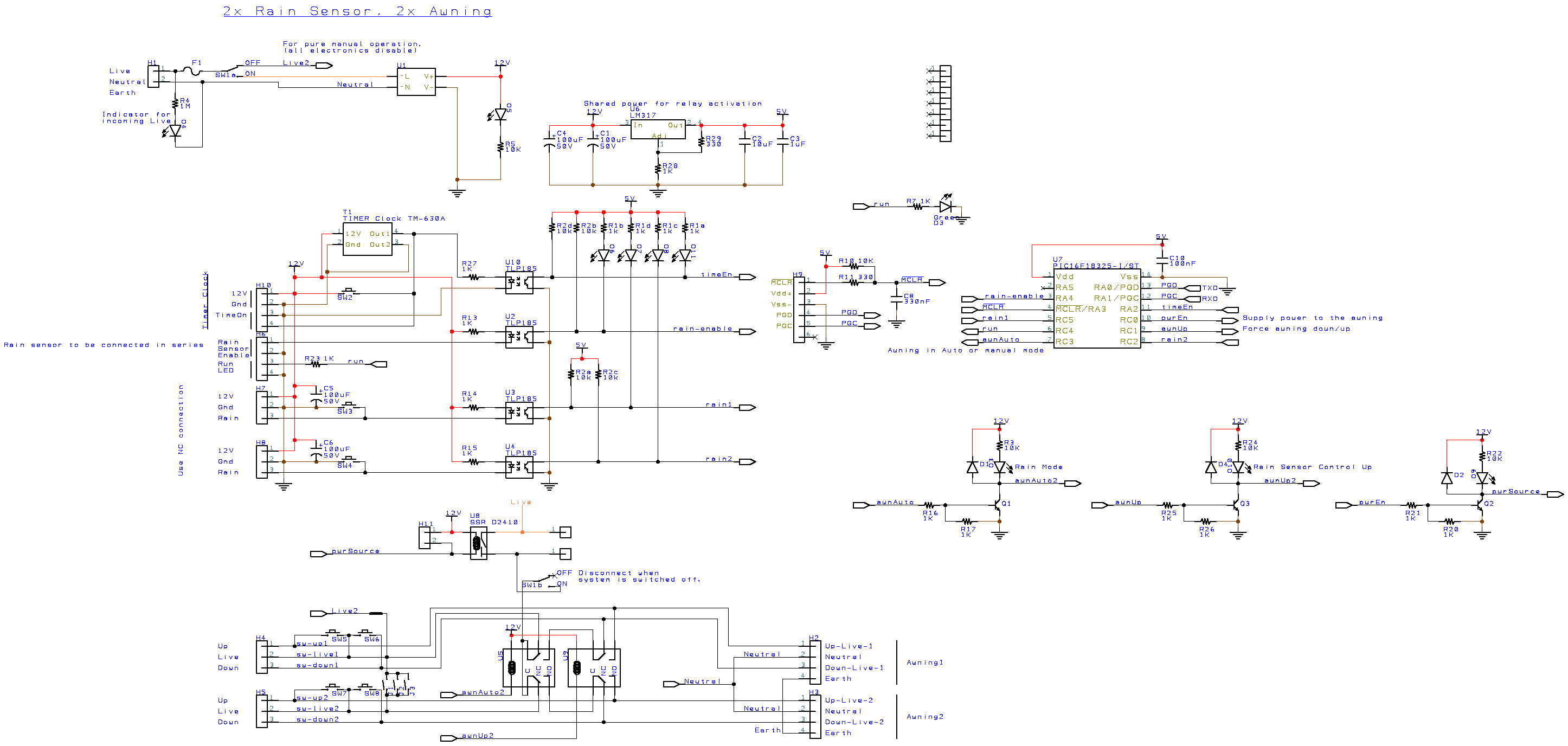
Rain awning schematic

Main Switch Function

The Neutral line is common to all. Live1 is the AC power line when the main switch is in On position (switch is downwards). This will activate the microcontroller and rain sensing electronic to function.

When the main switch is in the Off position (switch upwards), the entire electronic is not power up, and is not in operation. You will only see the green LED for 230Vac faintly lighted up. The rest of the LED are off. In this position the awning get access to direct power connection. This is as if the awning system works manually as normal. The Rain sensor controller is being by-pass. This allows for direct troubleshooting works on the awning without involving the rain sensing controller.

Relay U5

The function of this relay is to divert the incoming 230Vac (through the solid state relay U8) to either the manual control wall switches or to Relay U9 which forces the awning to open up, or roll up. Default relay position is allow manual control from the wall switch.

Relay U9

The function of this relay is to force the awning to open or roll up when Relay U5 is activated. Default relay position is to force awning to open its shelter for sheltering from the rain.

Solid State Relay U8

The function of this relay is to switch off the 230Vac power source while the relay U5 and U9 takes their time to switch. Doing this can prevent the mechanical relay U5 and U9 from contact welding problem. Meaning the relay switch becomes sticky because of the high voltage spark created during the switching. It improve the life span of the mechanical relay.
Reference

Contact us for further details.

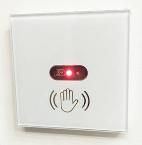
Touchless Lighting Wall Switch

Touch-less lighting wall switch. Switch On/Off your room lighting without touching the wall switch.

Suitable for installation at public area or high traffic user premises.

Reduce germs bacteria virus condemnation.
Minimise touch surface that can have direct contact with Covid virus.

Touchless Lighting Wall Switch
Video Demonstration

Build-in electronic IR sensor is sensitive to hand activation on the wall switch. Wave one time to turn on the lights and wave again to turn it off.

Simple and sensitive touchless hand wave wall switch sensor. Very simple to use.

Contact us at sales@pic-control.com for further information.

Check out our series of touchless contactless electronic wall switches for your other application.

Trellis Automated Roof Panel System

Product by Sunshade Trellis System Pte. Ltd. (Singapore)
Visit website: https://sunshadetrellis.wixsite.com/home

Introduction

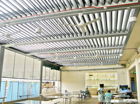
Automatic motorised Trellis system to shelter you from wet rain and hot sun shine, while you still get the fresh airy breeze. Louvered roof panel system installed with a rain sensor to automatically close the panel when it rains.

Installed Examples of Trellis Roof Shade System

Airy indoor open space using Trellis roof system.

The trellis roof can also be installed for indoor/outdoor balcony to create a spacious cool and relax area.

Feel the outdoor air breeze without too much hot and sunny sun shine. Nice natural lighting and cool open space.

This aluminum roofing system is designed to be light weight yet robust against strong wind and rain fall. Suitable for indoor and outdoor installation.

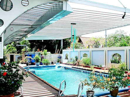
Trellis open close roof shade system for outdoor swimming pool.

Trellis roof system provides shades for your outdoor pool during a sunny day as well as raining days.

When the weather is good, the trellis can be open up to allow for shine and breeze through the open area.

Enjoy your pool with comfort.

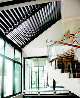
Trellis shade roof system for indoor corridor.

This is an indoor trellis roof canopy structure installation for a corridor inside the house.

Allows outside natural light and air breeze to enter into the house.

Makes the house cooler, brighter while using less energy.

The rain sensing mode will automatically close up the trellis to ensure that your indoor environment is keep dry and clean.

Operating Instruction

The trellis roof control is simple to operate. One button to open and another button to close the trellis.

The trellis system also comes with a rain sensor. When rain is detected, the trellis shelter can automatic close up itself so that your corridor stays dry.

An optional external buzzer can be install for auditory feedback to the user.

Opening Closing Trellis

A single push and release on the open button, the trellis will open to its preset half opening position. This preset position can be adjusted form the blue color POT on the circuit board. Another push and release will fully open the trellis.

A single push and release to the close button will fully close the trellis.

For controlling of the trellis opening to your preference, you can simply push and hold the button, to open/close the panel, and release the button when the panel reaches the position that you want.

Rain Detection

Rain detection mode can be activated to automatic control the trellis when it rains. The trellis will automatically be closed and do not allow to be open until the water gets dry out.

To open the trellis manually while the trellis is still wet, you have to switch off the rain detection mode first.

User can select this rain detection mode via a switch. The rain sensor mode indicator will get light when this mode is selected. When it is in OFF mode, the indicator will be turned off. This indicator will blink when rain is detected. If the rain mode is switched ON, the lighted indicator will starts to blink when rain is detected. Even if the rain mode is switched OFF, the indicator light will still blink when rain is detected, just that the blinking rate is slower.

System Connection Wiring

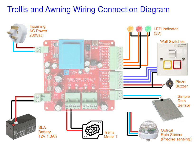
This section shows how

Wall switch to open/close the Trellis and to set for rain sensing.
Wiring Connection Diagram (for single bay Trellis installation)

Low cost rain sensor can be connected to this board to detect raining event. If the rain sensing mode is active, the trellis will automatically close itself to shelter away from the water. If you like the trellis to reacts faster to the rain, you can choose to install optical rain sensor instead. It is more precise in the rain sensing and can react faster to raining and rain stopping. You can order optical rain sensor from PIC-CONTROL.

Trellis Roof Controller Board

This is the main controller board for the trellis automated roofing system. It is the main board for driving the geared DC motor of the trellis system. Design to drive geared DC motor with a rating at about 1A (when it moves), and a stall current at about 8A to 10A.

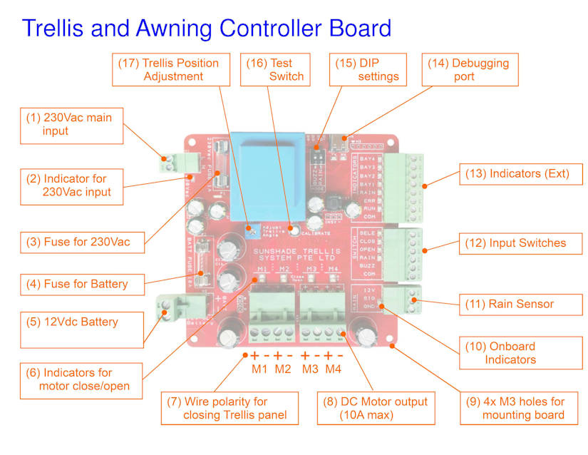
The following is the description of the controller board.

Electronic controller circuit board for Trellis Roof Shade System.

(01) 230Vac mains incoming power input

230Vac is required for charging of the SLA battery.

(02) Indicator for 230Vac incoming power

Green indicator will gets lighted up when there is power coming from the 230Vac input.

(03) Fuse for 230Vac

Fuse of 1A is recommended for protection from the 230Vac incoming mains power source.

(04) Fuse for Battery

Fuse of 10A to 15A is recommended for protection from the battery.

(05) SLA Battery

Sealed Lead Acid Battery. Recommending 12V 1.3Ah capacity battery (97 x 43 x 51mm). Larger size 12V 7Ah SLA battery (152 x 66 x 94mm) can also be use.

This battery is used for driving the DC motor of the Trellis.

(06) Indicators for Trellis motor

When the controller is driving the Trellis motor to close, Green indicator will gets lighted up. For opening of the Trellis, Yellow indicator will gets lighted up.

(07) Motor Wire polarity (closing the Trellis)

Motor wire polarity for closing the Trellis panel is motor positive terminal on the left (pin 1), and negative terminal on the right (pin 2). Apply this polarity should activate the motor to close the Trellis.

(08) DC Motor output

DC motor output is design for driving a DC motor up to a maximum current of 10A. Typical operating current is about 1A, and can spike up to 8A to 10A when the motor is in a stalled position.

(09) Mounting Holes M3 x 4

Mounting holes available at the 4 corner of the board. Design for M3 screw mounting. Distances between the mounting holes are about 91.5mm apart.

(10) Onboard indicators

Indicators onboard for technician monitoring and troubleshooting use.

(11) Rain Sensor interface

This interface allows a simple resistivity rain sensor to be connected via two wire, signal and ground pins.

It can also connect to a more sensitive and responsive optical rain sensor for a better user experience.

(12) User switches and buzzer interface

Switch buttons for user to control and beep sounder feedback.

  • Open Trellis
  • Close Trellis
  • Rain Sensing Mode
  • Bay Select
  • Beep Sounder

(13) External Indicators

User indicators for operation and monitoring.

  • RUN
  • ERROR
  • RAINING
  • BAY 1 (available in 4 bay controller board)
  • BAY 2 (available in 4 bay controller board)
  • BAY 3 (available in 4 bay controller board)
  • BAY 4 (available in 4 bay controller board)

(14) Debugging port

USB debugging port for monitoring purpose. It is a virtual serial communication port with the following settings,

  • baud-rate 115200bps
  • No Parity
  • 8 Data bits
  • 1 Stop bits

(15) DIP switches

— Not available —

(16) Test switch

— Not available —

(17) Trellis position adjustment POT

When the open button is pressed for the first time from the Trellis panel closed position, the panel will open to the half open panel position. This half open panel position can be adjusted to your preference by adjusting this (17) Trellis position adjustment POT.

Battery Power and Protection System

The whole system is powered by a 12Vdc SLA Battery (Sealed Lead Acid Battery). A battery capacity of 1.3Ah is enough for typical operation.

The charging of this SLA battery is supplied via the 230Vac power input. This power do not supply power to the trellis. It is only used for charging the connected SLA battery. If the SLA battery is not connected, the system will not be able to operate correctly. This 230Vac do not have enough power to drive the trellis motor. A 1.3Ah SLA battery capacity can drive the Trellis for about 30min to 60min without any charging. It is ok to install a high capacity battery if want the system to operate longer when AC power is not available (A power blackout scenario).

A battery monitoring is designed onto the system. If the voltage level of the battery falls below a healthy level, the ERROR indicator will start blinking. When this happens, the controller will only allow user to close but not open the trellis. This is to protect the battery from over draining itself, and to conserve the energy so that it can have enough power to close up the trellis when it detect rain. If the blinking appears, you can simply wait for a while. The battery will be charged up, and allow for normal operation again. This can happen when someone is operating the trellis for a continuous period of 30min or more, or if the battery becomes faulty after long use.

It is recommended to replace the battery every 4-5 years of operation.

The system ERROR indicator will appeared to blink faster if the battery is suspected to be faulty. If this happens, leave the system alone for 24 hours. If the ERROR indicator blinking persist, please contact for technical support. It could likely be cause by the following…

  • No incoming 230Vac power supply.
  • Faulty charging circuit.
  • Battery is faulty (normal wear & tear).

The technician will diagnose and help you rectify the problem.

Technical Specification

  • Board power consumption is about 1W, up to 12W max
  • AC Power Input: 230Vac 0.1A (for battery charging purpose)
  • DC Power Input: Sealed Lead Acid Battery SLA 12Vdc 1.3Ahr (for motor operation)
  • Output driver support geared DC motor of 12Vdc 1A (10A max rating)
  • Support low cost resistive, or high precision optical rain sensor.

Cable current capacity for the Battery and Motor can operate peak at about 10A. Cable gauge size of AWG16 is recommended.

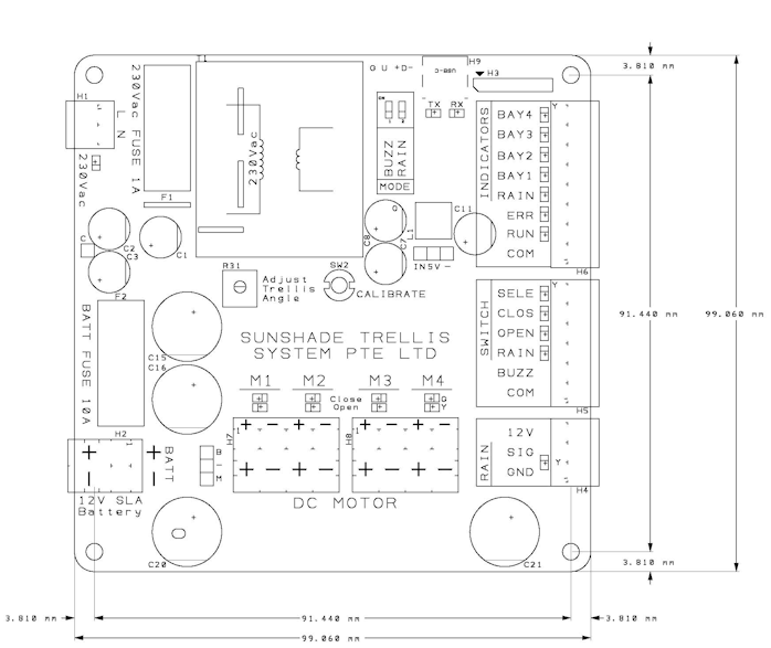
Trellis Controller Board Dimension

The physical board size is about 99 x 99 x 36mm.

Propose M3 mounting hole position is 91.5 x 91.5mm.
(mounting hole size is 3.2mm, suitable for M3 size screws)

Trellis Controller Board Dimension

The weight of this board is about 350g.

Deployed Site Installation

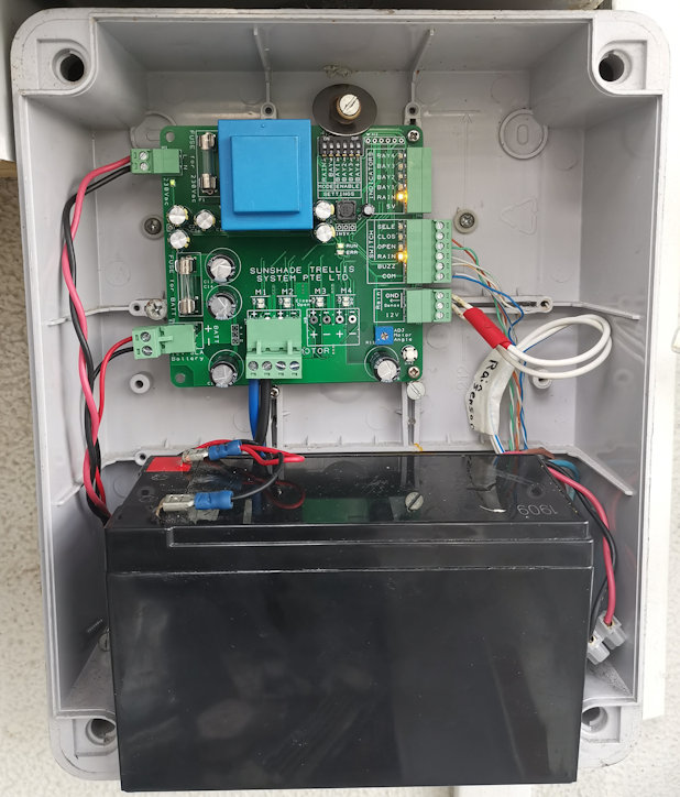
This is a installation for a single bay Trellis controller.

The board requires a 12Vdc Seal Lead Acid battery to function and for powering up the motor. Battery as small as 12Vdc 1.2Ahr battery can be use. (can continuously operates for about 45 minutes without the charging 230Vac power mains)

Trellis controller installation

Troubleshooting

Symptom ObservationPossible Cause
Error Buzz ToneThis is the most common feedback from a user. A low sound tone sounded when the switch is pressed. This can occurred when the Trellis is not allowed to be opened when it is raining and the rain sensing function is enabled.

Error buzz tone will also sound when you are trying to open the Trellis when the battery charge is low or the battery is faulty.
ERROR Indicator Blinking (slow).Battery voltage is low. Low in charge. This may also happen if 230Vac is not connected, or the charging circuit is faulty. If the system has been operating open/close action for long period of time, this may happen too. To conserve energy during this period, the Trellis can be close but cannot be open. You can wait for 24 hrs for the battery to be charged up before you can operate it normal again.
ERROR Indicator Blinking (fast).Battery voltage is super low. Battery probably needs a replacement.
Please call for technical support.
Cannot open Trellis.Check if ERROR indicator is not blinking. If it is blinking, read up the possible cause above. You can

If the Rain indicator is blinking.
The Trellis will not allow to be open, if battery level is low. You can wait for 24 hrs for the battery to be charged up, and attempt to open again.
The trellis will also not open if the rain sensing is enabled and water is detected. You can disable the rain sensing function, and open the Trellis.

If no indicator is blinking and the Trellis cannot be open, please call for technical support.
Cannot close Trellis.Please call for technical support.
Trellis do not automatically close when it rains.Please ensure that the rain sensing mode is enable.
If rain sensing mode is enabled and the Trellis do not close automatically when it rains, please call for technical support.

Board Voltage Measurement Test

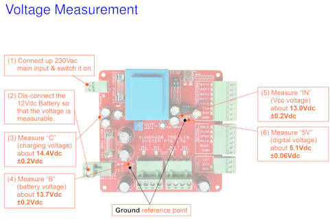
When doing this measurement to test if the board has all the voltage at the correct level, the battery has to be disconnected, and the AC main power input has to be switched on.

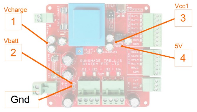
With reference to the Gnd pin, the voltage measured from the board labelled no. 1 to 4 should be as follows,

  1. Vcharge = 14.4V ±0.2V (battery charging voltage)
  2. Vbatt = 13.7V ±0.2V (battery voltage)
  3. Vcc = 13V ±0.2V (unregulated supply to the circuit)
  4. 5V = 5V ±0.06V (regulated supply to the circuit)
Checking voltage measurement point on the board.

Fast measurement tips:

The voltage different between point 1 and 2, point 2 and 3 is about 0.7V differences.

Contact Us for further details.

This system is designed and sold by Sunshade Trellis System Pte. Ltd.

Contact them at +65 6368 9800 (office phone), sunshadetrellis@outlook.com (email)

Click here to visit their website at https://sunshadetrellis.wixsite.com/home

Also check out other automated awning retractable roof shade system.

Compare NB-IoT with LTE-M

reference from
https://www.i-scoop.eu/internet-of-things-guide/lpwan/nb-iot-narrowband-iot/

LPWAN

DescriptionNB-IoT
(Cat-NB1)
LTE-M
(eMTC, Cat-M1)
LoRa
LoRaWAN
Sigfox
GPRSLTE
QoS (Quality of Service)LowHigher
Cellular TechnologyYes (using existing cellular network)Yes (using existing cellular network)No
(non-cellular LPWAN)
For mobile applicationNo (for static only)Yes (cellular switching)No
Latency1.6 to 10 sec100 to 150ms
In-door applicationBetterGood
CommunicationHalf-duplex Half-duplex
Devices talk less oftenDevices talk less oftenDevices talk more often
Good if only a few devices is expected to be used in the remote area.same as NB-IoTGood if many devices are deployed in area the same area nearby.
CostVery Cheap
$1/month
CheapCheapExpensive
Brand New methodLight version of LTE.

Telecom Connectivity Offer

Some of the offer from Mobile Network Operators (MNOs).

International Sim Card for NB-IoT connectivity

Evidence suggesting that NB-IoT is a method of using existing Telecom cellular network for IoT devices

Company supplying NB-IoT module

Other lists of manufacturer brands for NB-IoT modules can be found here,
https://www.gsma.com/iot/mobile-iot-modules/

<- Back to Bluetooth Resources Page

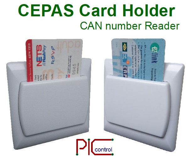
CEPAS Card Key Holder [PIC-345]

Wall-mounted cardholder that reads CEPAS card for authenticating user’s identity for the usage of facilities. Using CAN number is a convenient registration of the temporary guest user.

Application

  • Office room energy saving.
  • Meeting room usage.
  • Gym room booking.
  • Scheduled lecture hall lessons.
  • The authorised user of a facility.
  • Hotel card key energy-saving, and electricity control.
  • User guest registration.
  • Authorised operating of machines or system.

Features

  • Read the CAN number of a CEPAS card (Ezlink or NetFlashPay)
  • Communication RS485 (other mode is available, RS232, Wiegand)
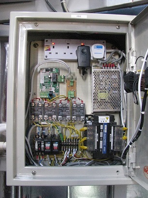
  • Optional board for network communication and power switching through the mechanical or solid state relay.
  • Operates from 12V

Dimension

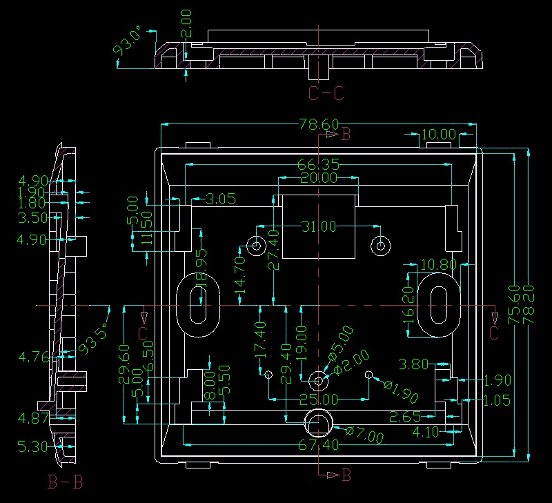
Face Plate size 86 x 86mm
Face Plate Dimension Drawing

Wall Mounting Method

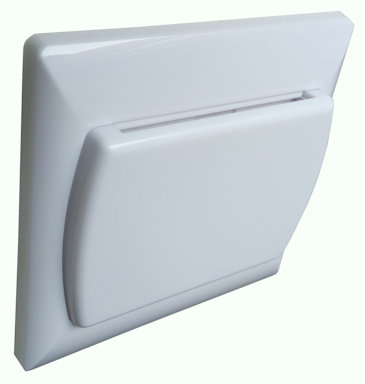
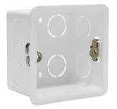
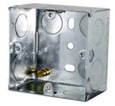
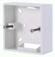
This CEPAS card key holder is to be wall-mounted like a typical light switch in Singapore. It can be flush/surface mounted onto the standard 86 x 86mm wall box.

Wall Flush Mount Plastic Box (86 x 86mm)
Wall Flash Mount Metal Box (86 x 86mm)
Wall Surface Mount Box (86 x 86mm)

Go back to CEPAS card reader product page.

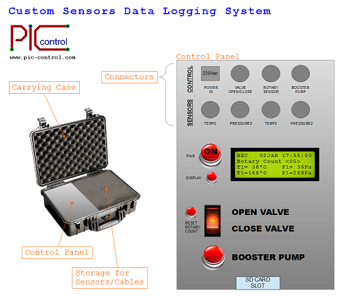
Sensors Data Logging

Data logging system design for sensors monitoring and test data recording. PIC-CONTROL can custom design a logging system specifically for your business use.

Sensor data logging system. Custom Design.

Sensor Data Logging Features

  • Type of Sensor Interface
  • Data Log Interface
  • Time-stamp of Data Logged
  • Power Supply

Type of Sensor Interface

There are many types of sensor connection interface.

  • Voltage ranges 0-3.3Vdc, 0-5Vdc, 0-10Vdc
  • Current interface 4mA to 20mA (Old standard, but still commonly used)
  • Digital communication interface, I2C, SPI, USART, RS232, RS485, Ethernet
  • Wheatstone Bridge

Data Log Interface

There are a number of data interfaces to choose from. It depends on your application.

Data collecting using a memory card is suitable for a standalone application where you want to leave the system to do the measurement or monitoring. You can collect the data at a later time, and open the file with your Microsoft Excel or OpenOffice Calc software for manual data analysis. The logged data can be presented with a timestamp for your archive. The amount of data collected will depend on the data being logged, the memory size of the storage and the time frequency of each data sample.

For an application that requires real-time data collection or real-time data analytic, you should consider using Ethernet communication line. Ethernet communication system is also more efficient when you are collecting from a number of sensors deployed to various different location.

  • microSD memory card
  • USB Thumb Drive
  • Harddisk
  • Cloud Server, Webserver data storage
  • Ethernet communication network
  • Wireless WiFi, Bluetooth, XBee
  • USB
  • RS232, RS485

Wireless sensors and equipment for monitoring weight. Sensors’ data are being transmitted via the internet for data logging to the cloud server.

XBee wireless sensors collecting data and sending them to the internet cloud.     Weight sensor monitoring through the internet WebService.

Timestamp of Data Logged

Date and time logging is typically necessary for analytic. This is also known as the data timestamp. This is especially useful for fast changing sensor data. Data logged can be archived for future reference.

Power Supply

The recommended method of powering up the data logging system is to use the wall mains 230Vac power supply.

For outdoor data collection, you may like to have your data logging system plugged to your vehicle for power or have it powered up from a battery.

A logger system can have the battery built in. There is a limit to how much power a battery can supply. For longer data collection usage, a large size battery will be needed. It usually means more bulky and heavy. There will be a charging function to charge up the built-in rechargeable battery.

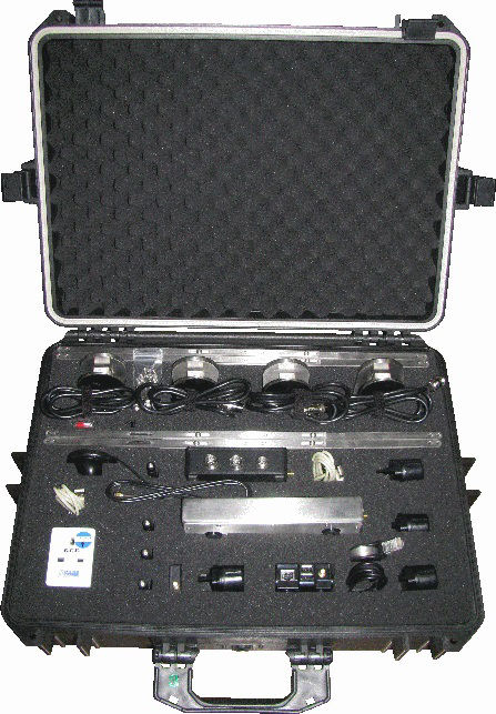
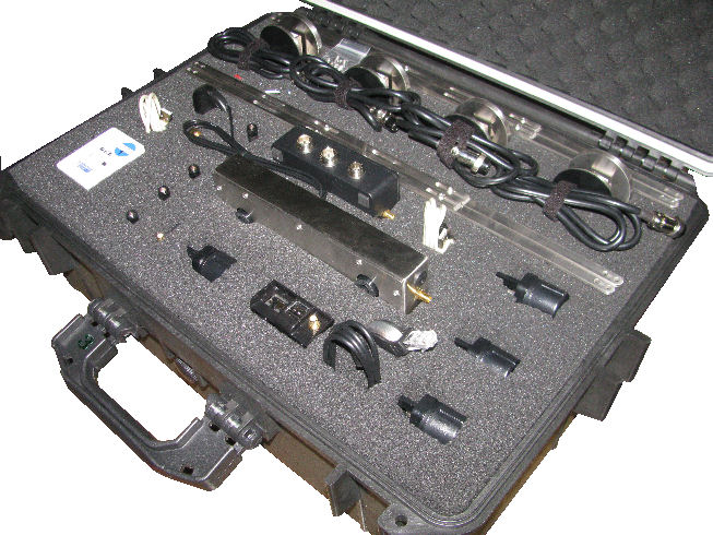
Sensor Storage

Built case for storing sensitive equipment and dedicated sensors. Neat and protect against wear and tear.

Easy storage for your equipment and sensors

Custom Data Logging System

Email PIC-CONTROL today for your custom sensor data logging system. We are able to design and custom built the system for your business. Custom built set starts from S$2500 and above.

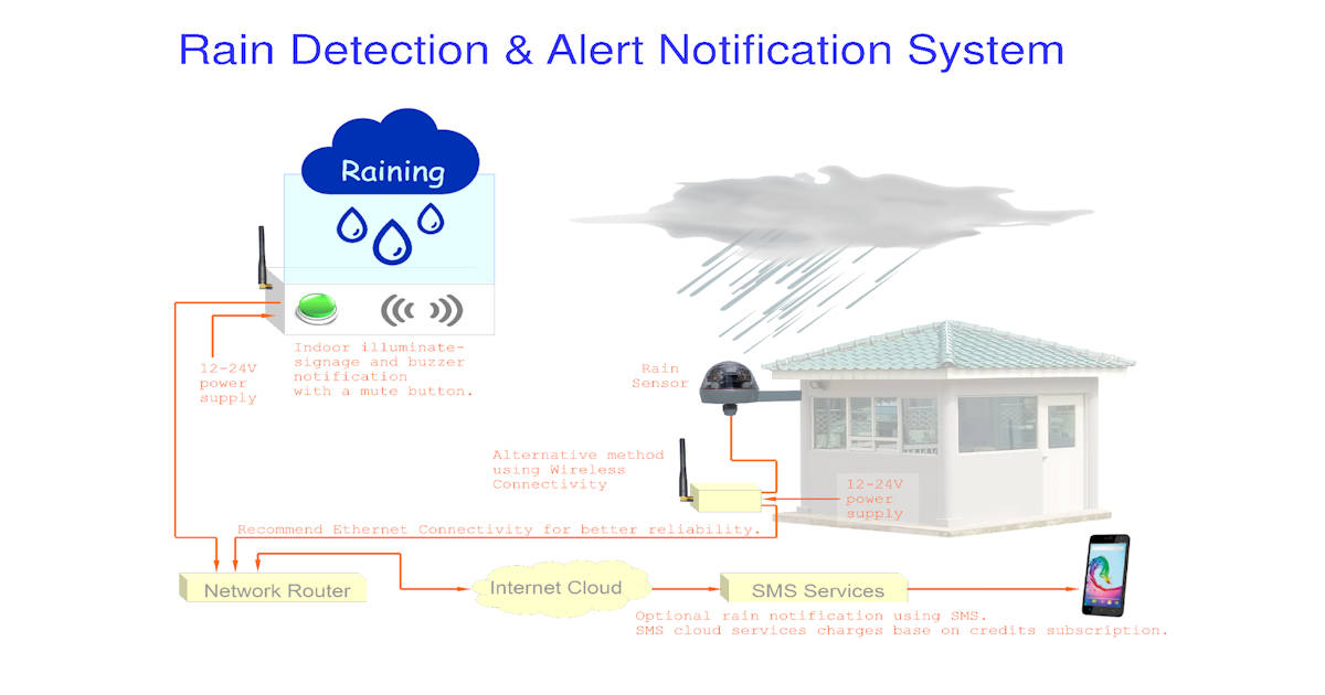
Rain Detection & Alert Notification System

Rain detection alert and notification system

Rain Detection (Alert Notification Process)

  1. The Rain Sensor that is installed outdoor detects raining.
  2. The indoor rain signage gets illuminated to indicate that it is currently raining outside.
  3. An alarm sounds to alert nearby personnel.
  4. Personnel can push the mute button to acknowledge the alert.
  5. The alarm can be muted, but the rain signage is still illuminated as long as it is still raining.
  6. Rain signage will be turned off when the raining activity is stopped for about 2 or 10 mins.
  7. The buzzer will not sound off again if the rain is stopped for less than 30 minutes.

Optional Features for Rain Detection System

Email Alert Notification

  • Email alert notification.

SMS Notification System

  • Option SMS alert using online cloud services.
    • Cheaper than traditional monthly SMS subscription sim card.
    • No need SMS modem or SMS sim card.
    • Requires SMS cloud service subscription.
    • Requires internet connection.

Wireless Connectivity

  • Wireless connectivity over 300-500m (in open space).

Rain Detection for Outdoor Premises or Activities

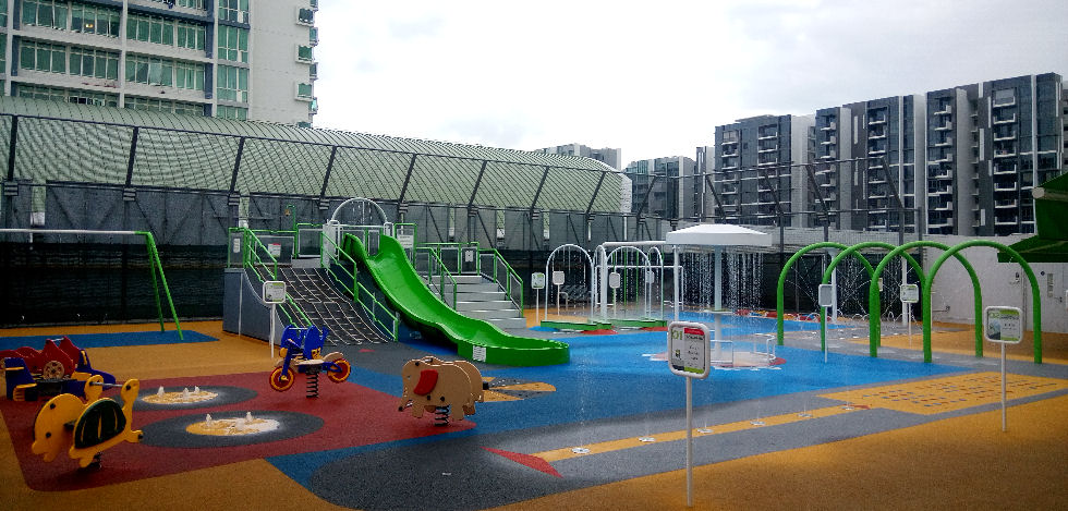
Rain sensor can be used to enhance the safety of outdoor activities. Outdoor play area can be deactivated when rain is detected to discourage children from their playing activities.

Rain detection for safe outdoor water play area activities.

Custom Rain Sensor Automated System

The rain sensor system can also be integrated directly with automated awning shade system, automated gate, door or window system.

It can also be used as a sensor to alert or halt outdoor aqua playground system to protect children from dangerous activities when the weather is bad.

Check out this page for more information about this wet weather rain sensor.

Contact PIC-CONTROL for further information on your automated rain sensor control system today.
Contact our sales for further information for a custom rain detection alert system.

Thermal Sensor

Thermal imaging sensor module

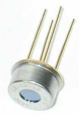
Thermal Sensor can detect the temperature of a subject without any physical contact. The technical name for the sensor is known as Thermopile Sensor. The sensor is able to detect the temperate of the surface of an area from a distance through the air. This is possible because the sensor is able to pick up the radiated heat in the form of IR (infra-red) from the subject.

Thermal Imaging Sensor is getting more and more popular compared to the vision camera. While the typical vision camera (CCD) picks up colour from the scene, a thermal camera picks up heat image. This helps the system to easily differential objects base on heat rather than colour. The thermal sensor is often used to detect dangerous hot surrounding and also to detect the presence of people. A technical name for Thermal Sensor is known as Thermal Array Sensor.

mini thermal sensor

Thermal Array Sensor is low in resolution compare to the vision colour camera. A high-resolution version (Thermal Imaging Camera) is still quite costly. Thermal array sensor (low resolution) is a more cost-effective sensor and is enough to serve its purpose.

Temperature sensor

Thermal Array Sensor Available in the Market

D6T-44L-06 (4×4 pixels), D6T-8L-06 (8×1 pixels)

datasheet: thermal-array-sensor-d6t.pdf

D6T-xxL-06 is available online from element14, Mousers Electronics or Digi-Key Electronics


TPA81 (8×1 pixels)

datasheet: thermal-array-sensor-tpa81.pdf

TPA81 is available online from sgbotic or Robot Store (HK)


Grid-EYE, Infra-red Array Sensor, AMG88xx (8×8 pixels)

datasheet: thermal-array-sensor-grid-eye.pdf


PIC-CONTROL customised the electronic solution for your businesses. For thermal sensing application and inquiry, you can contact our sales engineer or visit our website to learn about our other electronic engineering services.


Observatory Dome Automation Control System

Dome Automation Control for Astronomy

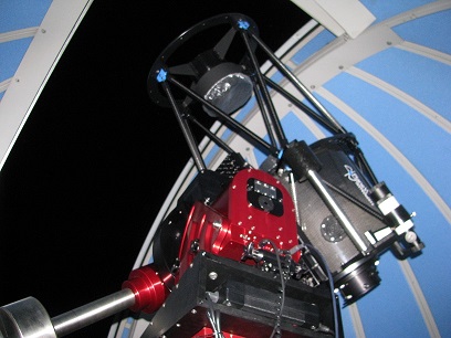
automated electronic controlled dome slit telescope

Astronomy Automated Control for
Observatory Dome

by STAROPTICS.

Customised integrated dome control system with the astronomy software “TheSkyX Pro” from SOFTWARE BISQUE and “Boltwood Cloud Sensor 2” from Diffraction Limited.

automated electronic controlled dome slit telescope

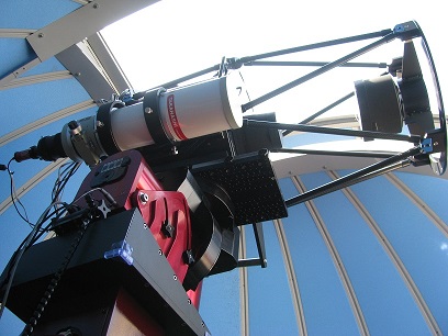
Paramount ME Mount II (Equatorial Mount) for the telescope, inside an Observatory Dome Motorised 3.0m Steel Astronomical Dome.

integration for dome control software

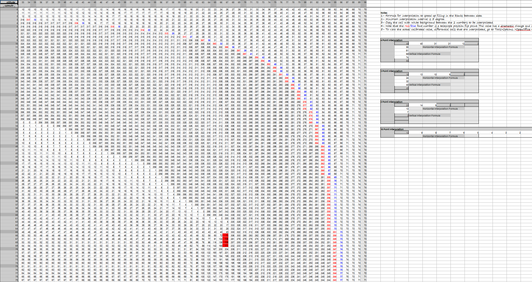
The Paramount ME Mount II is big and filled with many advanced features for astronomy observation.The multiple axis equatorial mount poses a problem when deployed in a small and tight observatory dome. The mounted telescope and its allowed movement are as big as the dome’s space available. The default dome azimuth generated from the SkyXPro software is not aligned with the telescope view.Software Re-mapping of Dome slit opening position to cater for any form of automated telescope system which the scope vision is offset from the centre of the small dome.

Dome Azimuth Mapping File to align the dome slit to the correct direction.

Screen capture of the dome’s azimuth mapping file. This mapping file ensures that the dome slit opening is always following the telescope mounted on the Paramount ME Mount II.

electronic dome automation system integration

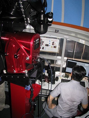
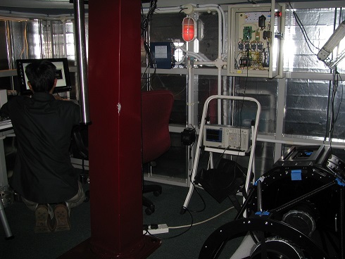
Testing and commissioning the dome control system.

Java Program to Automate Observatory Dome Control

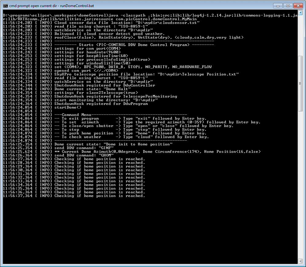
Java running at the back end controlling the hardware of the dome automation system.

automation electronic for the controlling the integrated dome slit

Junction box for Automated Dome Controller. The controller uses solid state controller (no mechanical wear and tear, no mechanical noise), long operating lifespan.

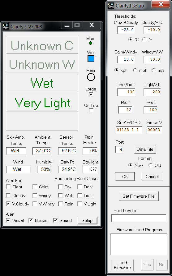
Weather Sensor for Observatory Dome Automation ControlWeather Sensor Status Report

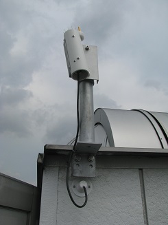
Boltwood Cloud Sensor 2 weather and rain sensor to ensure that the telescope is protected from the bad weather.

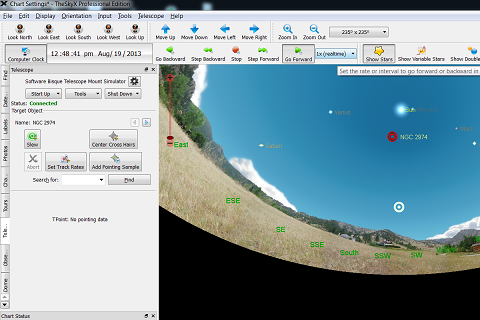
SkyXPro Software Telescope Control Interface

SkyXPro Telescope and Dome control software interface.

Contact PIC-CONTROL today
for your Automation Control System Integration.

Feel free to contact us.

pic-control logo