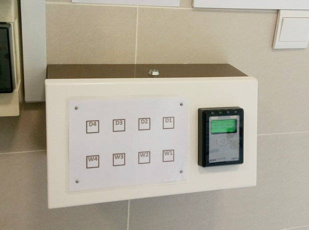
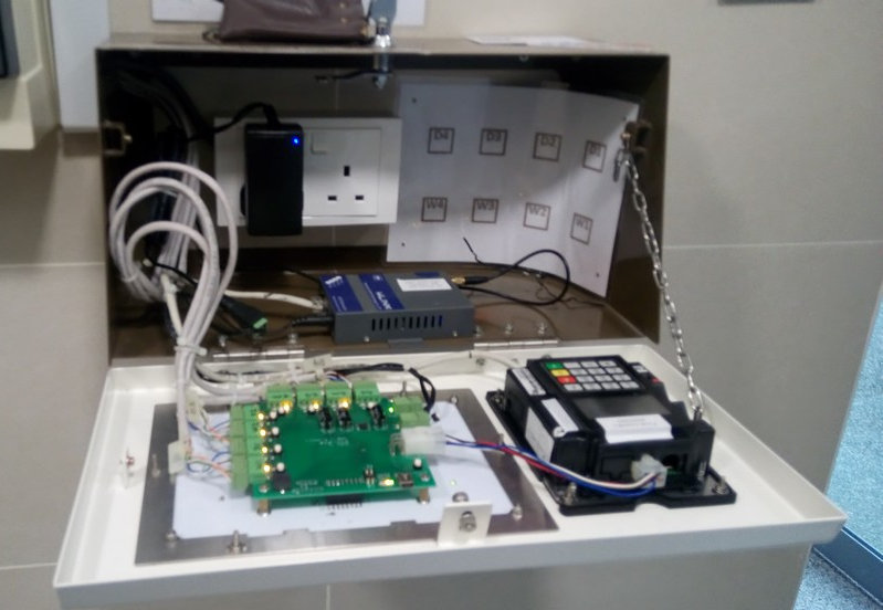
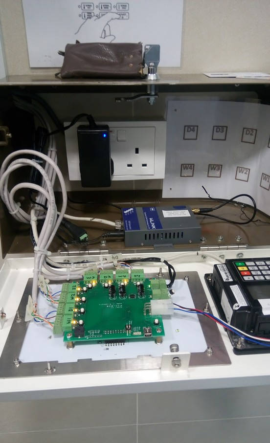
Example of an Installed Payment System
This is an illustration of an installation done. There is no network point in this illustration as it is using a 3G modem for communication instead. The cables are pulled into the enclosure via the cable entry hole channel on the left side of the enclosure.
In a typical setup, the following 3 type of cables has to be laid.
- Dual ganged power socket.
- Network point socket.
- Cables from machines to this payment terminal enclosure.
Enclosure Installation Height
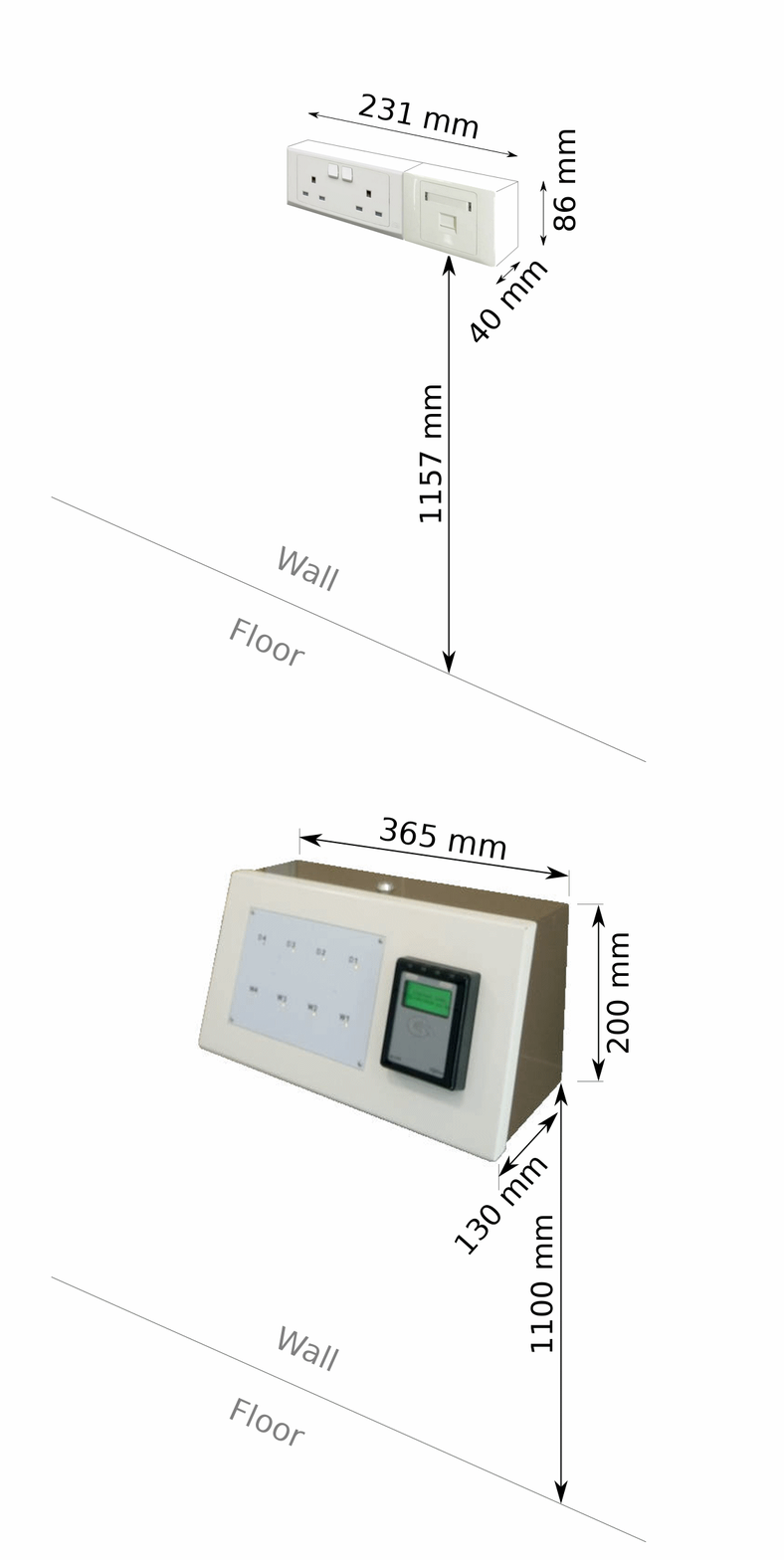
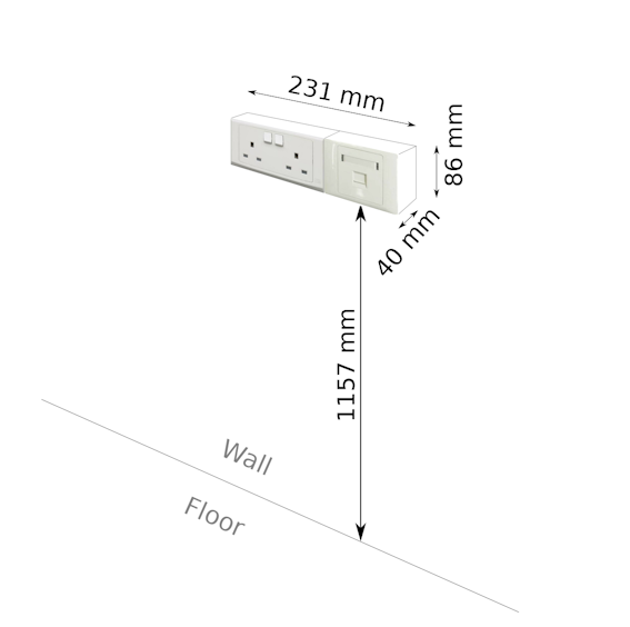
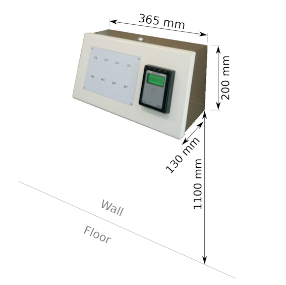
The recommended installation height of the power/network socket point is about 1157mm. The enclosure will be installed after power/network sockets are installed. The enclosure will cover directly over the sockets and cable trunking.
The position of the sockets will be the center location of the enclosure. The installed position of the sockets will determine the position of of the payment terminal.
Install the sockets/enclosure at a comfortable and ergonomic high for your user.
The following information provides the internal layout of the casing.
Power Point & Network Point Installation
The payment system requires a minimum of 1x power point and 1x network point. A spare power point is recommended for future use.
Resources to Provision:
- 2x Power Point
- 1x Network Point
The following is the dimension of the enclosure covering the power point and network point. The opening from the enclosure is about 298 x 120mm. Space is tight. Please ensure that there is enough space for the enclosure to cover over the power/network points on the wall.
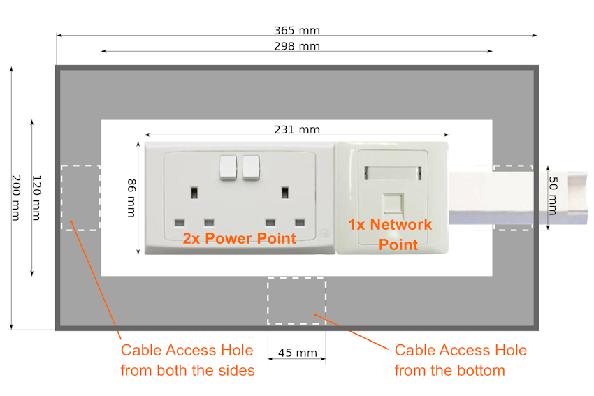
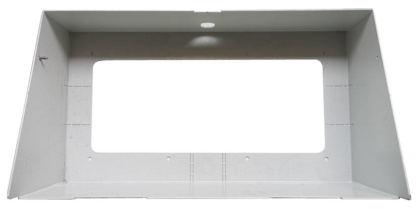
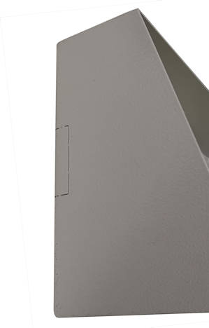
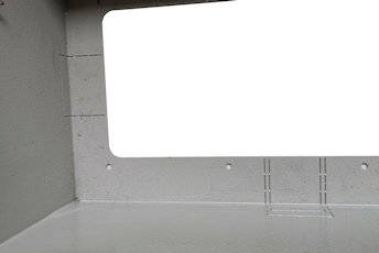
Please note that there are 3 pre-designed hole channel for cable entry. Two are located by the sides and one at the bottom of the enclosure. The hole channels are aligned to the ceter of the enclosure. It is recommended not to have the cable entry coming from the top of the enclosure, nor the trucking be laid across the top of the enclosure. This is for aesthetically pleasing reason. It will look nicer to select the cable entry channel location to a position that is not too visible. The best entry location will be from the bottom of the enclosure.
The standard width of the hole channel (max) is indicated on the layout above. The holes are design base on the commonly available cable trunking found on the market. Suitable for small and big cable trunking.
There may be situation where the 3 standard hole channel on the casing may not be big enough for the trunking deployed. If the trunking size is bigger than the standard hole channel on the casing, the hole channel will have to be manually enlarge to cater for the massive chunk of wiring.
Cables from Washer/Dryer machines to Payment Terminal
Cables are required from the machines to the payment terminal location. This is to allow the payment system to trigger the machine after the user successfully made their payment.
Cable range AWG20-25 (multi-strand) is recommended. CAT5 cables is easily available and is also fine to use.
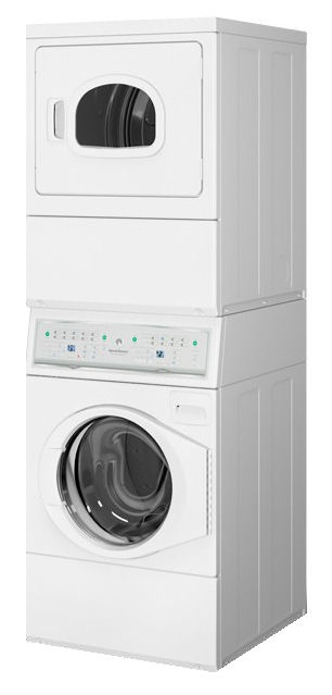
Estimate about 1 cable per Washer/Dryer stack. It is recommended to lay a spare cable for every 2 stacks of machine. There are a lot of vibration from the machine, and it is possible that wire may break after long use. This is especially for Cat5 cables as they are only of a single strand. Therefore spare cables is recommended.
These cables will be laid all the way into the enclosure together with the power/network socket. There is no need to terminal these cables. Just leave it dangling with an extra length of about 500mm will.
Network Port Settings
The payment terminal communicates over the internet for all payment transaction. When using local network point that is protected by the organisation firewall, some of the port number needs to be open so that communication needed by the transaction can proceed.
Please contact us for further details of the exact network port to open.
Use Ping.exe program to test data route to ensure that the port is open on the network point.
Common mistakes and problem faced
Here are some of the commonly mistakes and problem that makes the installation
- Power socket point and Network point has to be installed in the middle of the casing position. The back of the casing has a hole opened for power point and network point. Please position the power/network point socket in the middle where the casing has to be installed. Always install them to the middle of the casing enclosure.
Precaution for Recessed Installation (not surface mounting)
- Please ensure that there are no obstruction to the path of slotting the casing into the recessed hole. All wiring and termination has to be behind the wall, and in to middle of the recess hole position.
- Have a wooden frame made to size, for the casing to slot in. This frame provides a stronger support and makes it more precise for the casing to fit it. Casing can then be used to secure the casing firmly onto the frame. Gypsum plasterboard should not be used as a frame for the casing. The soft powdery structure is not suitable to hold the casing.
Wiring & Connection
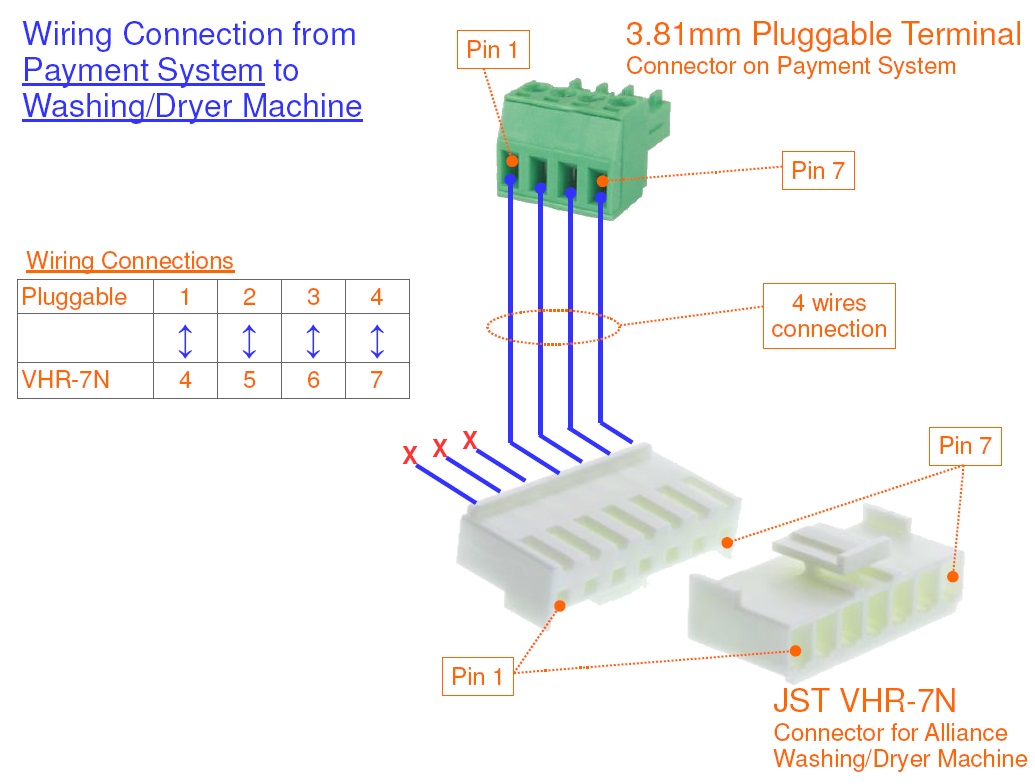
Wiring and connection for speed queen washing/dryer machine.
Wiring color code
The following is the propose color code of the wiring assuming that a CAT5e network cable is used.
| Pluggable Screw Connector | CAT5e wire color code | VHR-7N Connector |
| Pin 1 | Orange/White | Pin 4 |
| Pin 2 | Orange | Pin 5 |
| Pin 3 | Green/White | Pin 6 |
| Pin 4 | Green | Pin 7 |
Board Description (MDB Payment Interface Board)
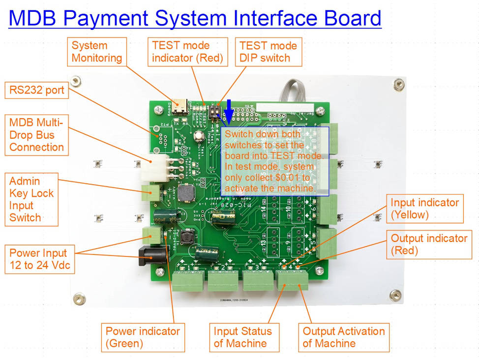
Testing with $0.01
Click here for payment system testing procedure with your credit card or cashless card.
Restarting the payment system.
There are two touch button assigned to the payment system to restart the system. It is usually the last button and the first button on the touch panel.
On a 8 machines payment board set, the default buttons are W4 (last button), and D1 (first button). Simply press and hold W4, followed by pressing and holding D1 button. Hold both button until you hear a short beep, followed by a long beep, then you can release your finger.
You should be able to see the system doing a full power off, and on restart process.
For IUC180 payment terminal, you will need to wait for about 10sec before terminal is ready for use.
For IM30 payment terminal, you will need to wait for about 2-3 minutes for the terminal to establish the internet connection before you can start using it.
Clearing Credits on the Washing Machine
This procedure is for fast forwarding or skipping the washing machine operating procedure. This is needed to help clear the credit triggered on the machine.
A quick paragraph to summaries the procedure. Simply ensure that the bypass switch is activated (disconnected or open circuit), press and hold button 1 & 2 to enter into the maintenance mode “rAPd”. Press “Start” button until the whole process ends.
The detailed procedures and explanation is as follows,
- When the machine is idling, the display panel shows “100” indicating the credit of $1.00 required to start the machine.
- After the payment, the machine will response with a beep with number changed to 30 (representing 30min of washing) This indicate that the machine has accepted the payment.
- Open the front panel with a physical key.
- Disconnect the bypass switch. This bypass switch allow us to go into the maintenance mode. With the machine bypass activated, it will also not record any transaction or operation to this machine. If you can see a sensor switch which detect the panel open, this is also known as the bypass switch. The washer (left side), dryer machine (right side), each has their own by pass switch.
- Press and hold button 1 & 2 (the left side buttons, top and button). It will go into maintenance mode with the panel displaying “rAPd“.
- The front loading door has to be close in order for the machine to cycle through the wash cycle.
- Press the green Start button to fast forward the whole washer process. This reduces the timing on the machine. You will see the number 30min reducing. Keep on pressing until the value becomes 1, then wait for a few second for the machine to react, and a final press will get the machine time to becomes 0.
- Open the door to complete the whole process. The washing machine will reset back to machine idling state. This panel will display “100” again, and the machine status will become available for the next transaction to take place.
- Do remember to restore back the bypass switch before leaving the place. Test to check that the machine cannot enter into the maintenance mode by press holding the button 1 & 2.
Price Settings on the Washing Machine
- Open the door for 2 sec and close it back to go into the configuration mode.
- Press and hold button 1 & 2.
- You will enter into “rAPd” menu. It is a bypass operation.
- Press button 3 & 4 (up/down button) to scroll through the menu.
- Scroll to the menu item Prog. Then press button 5 to enter.
- Scroll to the menu item AtS, then press enter.
- Scroll to the menu item 0, then press enter.
- Then the price setting will be displayed. Example for $1, it will be 0100.
- Press button 3 & 4 to change the price.
- Press enter to go to the next digit until the price is entered.
- Then press button 2 (back key) to escape all the way to the operation mode.
Troubleshooting Problems
Error messages on the payment terminal iUC180
- “REFUSED (XX) REMOVE CARD“
Network connection issue with the payment.
Resolved by resetting the payment terminal, or do a manual settlement to see if the problem go away. - “OCBC CABLE UNPLUGGED NETWORK ERROR“
Ethernet cable unplugged - “OCBC NETWORK ERROR“
Local Area Network issues, LAN port not opened for the bank. Communication error.- Test using Telnet command via the Win10 Command Prompt
- telnet 43.245.17.122 15443
- telnet 43.245.16.210 15443
- (both should show a blank screen meaning network connectivity is there)
- Test using Telnet command via the Win10 Command Prompt
- “DRMS NETWORK ERROR“
Network DHCP issue. - “DRMS CONNECT ERR-1601“
socket creation error - “OCBC CONNECT ERR-1602“
- “COMMUNICATION ERROR“
should be board MDB communication error.
Some of the more common problems
- Network point is down
- Machine is not triggered
- Machine is not available for selection
- Cannot connect to payment gateway
Maintainance mode on payment terminal iUC180
QR Code
QR code can be found on the system which will lead you to this page. (future implementation)
