Start up Guide.
Congratulations on your purchase of your MDB to Pulse Converter board.
This is a quick start-up guide to help you get familiar with the board.
- A quick glance of the board parts.
- Connecting to the Payment Terminal and Pulse-based Machine
- Do simple test to verify it working
Board Description
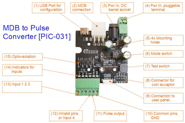
Factory Default Setup
The MDB to Pulse converter board can be configured for various kind of use-case scenarios. To help starter to have a quick test, this board has been set with a factory default to the Single Price mode.
Single Price mode is the simplest setup. It is designed for receiving a single price payment. The user simply tap/swap their card on the payment terminal, and the MDB to Pulse converter board will trigger a pulse to your pulsed machine.
We will use this mode to familiarise ourselves with the basic operation of this board.
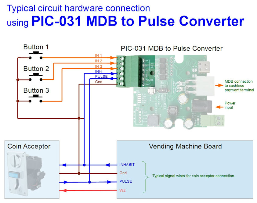
Connection for Single-Price Mode
These are the basic minimum connections needed for Single-Price Mode to work.
- Power cable
- MDB cable connection
- Pulse wiring to your machine
Power cable
PIC-031 MDB-to-Pulse do not take up a lot of power. It can accept voltage range from 9Vdc, 12Vdc up to 24Vdc.
The recommended power adaptor to use is the power adaptor provided with your Cashless Payment Terminal. The power adaptor will be connected to PIC-031 instead.
MDB cable
The Cashless Payment Terminal will be connecting to PIC-031 using the MDB cable connection.
Pulse wiring
This is the connection from the PIC-031 board to your pulsed-based machine.
You only need 2 wires connection on the PIC-031 board to your machine. That comes from the last 2 pins of the 6 ways connector on the PIC-031. The pulsed-out pin and the ground pin.
Other connection.
PIC-031 has another model with a coin-acceptor socket. This socket not only provides power to the PIC-031 board, it also contains the pulsed wiring. There is a total of 4 wires on this coin-acceptor cable. If you are using this, you can simply plug the cable onto the socket and to your machine directly. There is no need to supply the power adaptor for the PIC-031 board.
This is usually a 12V based pulse system. Your Cashless Payment Terminal should also be able to be powered up via the 12V. If this is not the case, then this coin acceptor socket shouldn’t be use.
Powering up the unit
Upon powering up the system, the PIC-031 board will communicate with the MDB based Cashless Payment Terminal. If the initial communication works out, the Payment Terminal should have a display indicating that the terminal is ready to accept payment.
Please note that the MDB Payment Terminal must be connected to the PIC-031 board in order for the board to work. If no MDB terminal is available for you to test with, you can still interact with this PIC-031 board for configuration.
Test your system
Now that the whole system is ready. Take your card and tap/swap on the terminal.
You can also press the test button on the PIC-031 board to send the pulse output to your vending/gaming machine.