Contents
Board Description
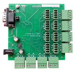
Board size is 100x100mm
Installation
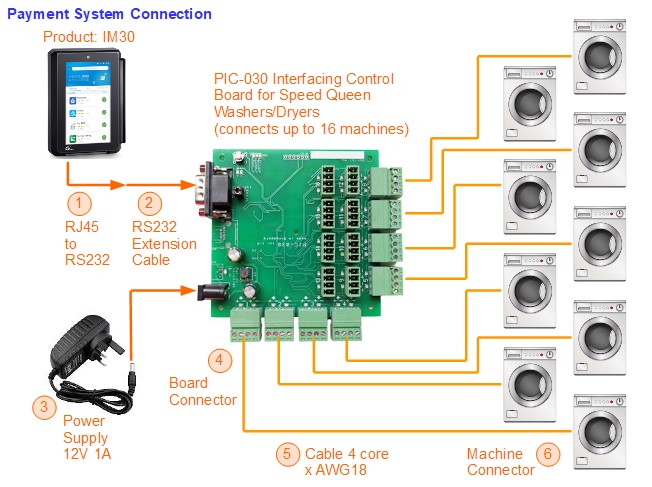
System Connection (Overview)
Parts Required
- Multicore Cable (4 core x AWG18 0.081mm2)
- Connector Housing and Pins (for SpeedQueen Washer/Dryer machines)
- Casing Enclosure
- (optional) Cable Gland
- PCB Standoff (for 3mm mounting hole)
- Communication Cable RJ45 to RS232 (female) from IM30 terminal
- Communication Cable Extension RS232 (male to female, 5m to 15m)
- Power Adaptor 230Vac to 12Vdc (1A), DC Barrel 5.5/2.1
Cable (4 core x AWG18)
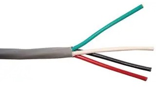
Cable connecting PIC-030 to the SpeedQueen Washer/Dryer machine.
- LAPP KABEL, part number: 0028704 (unshielded), 0034804 (shield)
- BELDEN, part number: 8489 060100 (unshielded), 5302FE 008500 (shield), 9418 060100 (shield), 5302UE 0081000 (unshielded ø4.67mm), 5302FE 008U1000 (shield), 6302FE 8771000 (screened), 9418 060U500 (shielded), 9418 060500 (shielded)
- ALPHA WIRE, part number: 1898/4C SL001 (unscreened), 1898/4C SL005 (unscreened, ø5.87mm), 79012 SL005 (unscreened), 25064 BK005 (unscreen)
Local Supplier: https://www.lhse.com/
Connector Housing and Pins (for SpeedQueen Washer/Dryer machines)
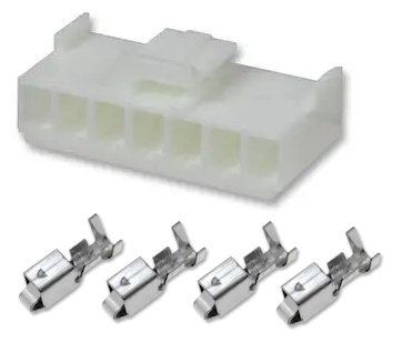
Connector to connect the cable to the circuit board on the SpeedQueen machine.
1x housing, 4x pins for each machine
Housing Part no.
- JST VHR-7N
- Molex 09-50-8071, 09-50-8073, 09-50-3071
Pins Part no.
- JST BVH-21T-P1.1 (AWG18-22), SVH-21T-P1.1 (AWG18-22)
- MULTICOMP PRO MP008511 (AWG18-22)
- Molex 08-50-0106 (AWG18-24), 08-58-0189 (AWG18-20), 39-00-0286 (AWG18-24), 08-50-0107 (AWG22-26)
Crimping Tool required for crimping the pins to the wire AWG18.
- JST WC 930
Alternative special housing from TE Connectivity AMP
- Housing (non-crimp type) 3-643820-7
- Dust cover 640643-7
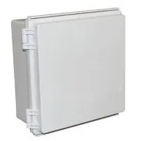
Casing Enclosure
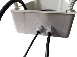
Cable Glands
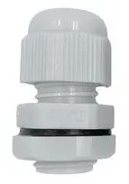
Optional Cable Glands for cable ø4 to ø6.5mm. For waterproofing the cable hole on the casing.
One piece for each cable to each machine.
- RS Pro 822-9644
PCB Support Standoff (for 3mm mounting hole)
To secure the PCB board to the casing.
4 to 5 pieces of PCB Support (for the mounting hole of ø3.2mm) for each PCB board or casing.
- Richco LCBSBM-3-01 (4.8mm height)
Communication Cable RJ45 to RS232 (female) from IM30 terminal
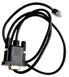
To purchase from MobileEFTPos. This cable brings out the RS232 interface from the Payment Terminal IM30.
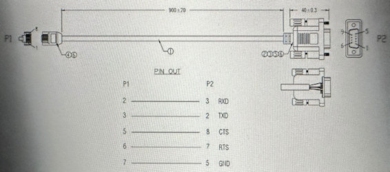
Communication Cable Extension RS232 (male to female, 5m to 15m)
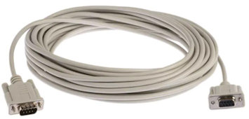
To extend the distance of PIC-030 board from the Payment Terminal IM30
- Roline 11.01.6290-25
Power Adaptor 230Vac to 12Vdc (1A), DC Barrel 5.5/2.1
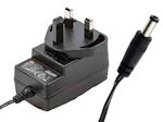
Provide power to the board.
- MeanWell 12V 1A (DC barrel jack 5.5/2.1) GE12I12-P1J + AC plug-UK
Hardware Installation
There are a total of 3 types of wiring to the PIC-030 control board.
- Power Plug
- Communication Plug
- Washer/Dryer Plug (up to a maximum of 16 plugs to the board)
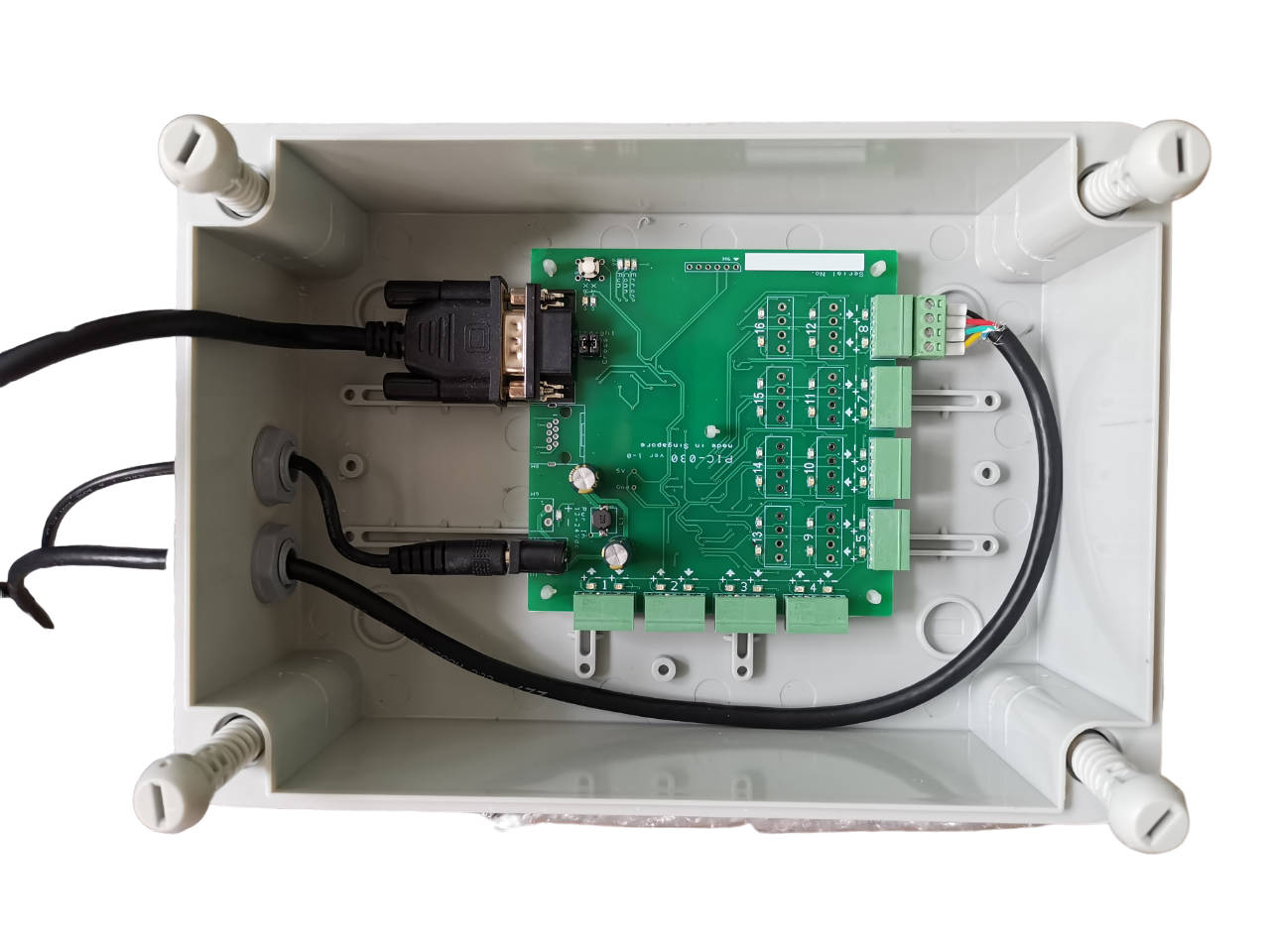
Power Plug
The board can accept a power plug DC barrel jack size of 5.5/2.1 OD/ID. This power can be from a wall power socket AC/DC power adaptor that provides a voltage range of 9Vdc, 12Vdc up to 24Vdc. The current rating is recommended to be about 1A.
Alternatively, you can also tap the power from another system to use it with this board. You do not need to buy an additional power adaptor to power up this board.
Communication Plug
The communication plug uses RS232 cable (dSub09 9pins connector male to female). The female connector side is connector to the board. The male end is from the Payment Terminal, connected to its cable extension (RJ45 to dsub09 female connector).
The maximum recommended cable length is 15m. If you need more than 15m, this will require the engineer’s support to check the quality of the cable and ensure it is wired up correctly.
Washer/Dryer Plug
This cable connects from PIC-030 board to a SpeedQueen washer/dryer machine.
You can connect up to a maximum of 16 machines to this board.
Wiring from PIC-030 board to washing/dryer machine.
Pin out of Plug (Screw Terminal) on the PIC-030 board
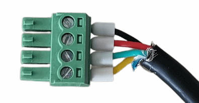
Pinout
Pin 1 (in+) – White
Pin 2 (in-) – Green
Pin 3 (out+) – Red
Pin 4 (out-) – Black
Pin out of Plug (JST VHR-7N) on the Washing/Dryer machine board
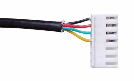
Pinout
Pin 4 (in+) – White
Pin 5 (in-) – Green
Pin 6 (out+) – Red
Pin 7 (out-) – Black
Test and Commissioning
Testing Tools Required
- Android Phone (USB-C with OTG function)
- Install Andriod APP (Serial USB Terminal)
- OTG cable (USB-C to USB type-A socket)
- USB (type-A) to RS232 (female) converter
- RJ45 socket to RS232 (male) converter (cross cable)
Setup Android APP (Serial USB Terminal)
Testing from Payment Terminal RJ45 Plug
Wiring for RJ45 Plug to RS232 (dSub09 male plug) Adaptor
- RJ45 pin 1 (blue)
- RJ45 pin 2 (orange) –> (data flow direction) is dSub09 pin 3 (TXD)
- RJ45 pin 3 (black) <– (data flow direction) is dSub09 pin 2 (RXD)
- RJ45 pin 4 (red)
- RJ45 pin 5 (green) is dSub09 pin 8 (CTS)
- RJ45 pin 6 (yellow) is dSub09 pin 7 (RTS)
- RJ45 pin 7 (grey) is dSub09 pin 5 (GND)
- RJ45 pin 8 (white)